Implementing user mode foreign device attachment to memory channel

a foreign device and memory channel technology, applied in the field of data processing, can solve the problems of data stored in dram, /b> sometime incur errors, data corruption, etc., and achieve the effect of not having negative effects

Inactive Publication Date: 2014-07-10
IBM CORP
View PDF2 Cites 9 Cited by
  • Summary
  • Abstract
  • Description
  • Claims
  • Application Information

AI Technical Summary

Benefits of technology

[0019]Principal aspects of the present invention are to provide a method, system and computer program product for implementing attachment of a user mode foreign device to a memory channel. Other important aspects of the present invention are to provide such method, system and computer program product substantially without negative effects and that overcome many of the disadvantages of prior art arrangements.

Problems solved by technology

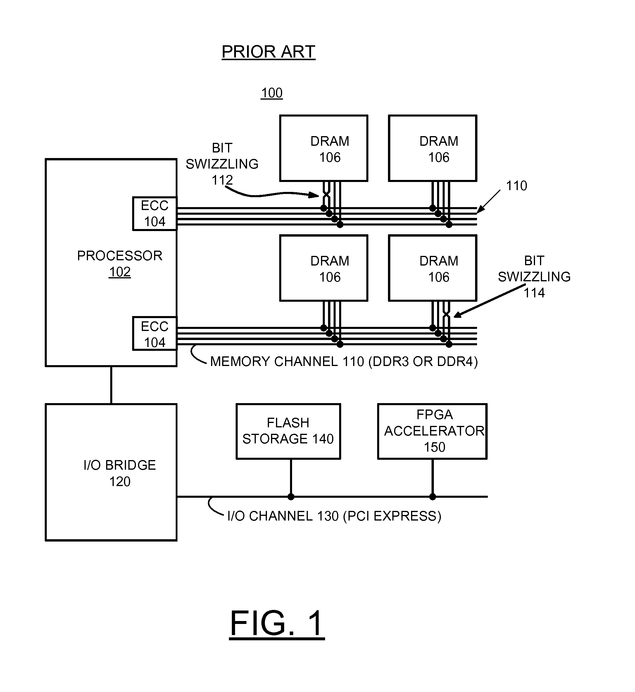
Data stored in DRAM 106 sometime incur errors with small probability due to environmental factors such as electromagnetic radiation, electrical noise and hardware malfunction.
If DRAM errors in a data word exceed design thresholds, an uncorrectable error, that is a data corruption, is said to occur.
However, unlike the I / O system, memory accesses are expected to be very fast, and expected to be completed in a single instruction execution time.
Since state of the art MMUs 302 are implemented in hardware, access rights checking is completed very fast, typically with time delays comparable to single instruction execution.
In densely packaged computing systems, there may be insufficient physical space for I / O adapters.
In some computing systems, the data bandwidth through the I / O channels may be insufficient as compared to the memory channels, because there are fewer I / O channels than memory channels, and furthermore, each I / O channel typically has fewer wires than the memory channel.
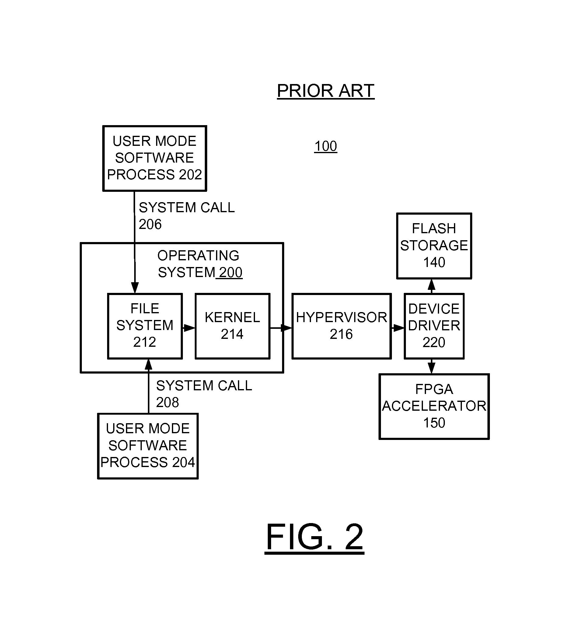
In some computing systems, the communication latency through the I / O channels may be insufficient as compared to the memory channels, because the I / O requests have to travel through several layers of software to verify access rights to the files and devices, therefore possibly requiring execution of tens of thousands of instructions.

Method used


Image

  • Implementing user mode foreign device attachment to memory channel
  • Implementing user mode foreign device attachment to memory channel
  • Implementing user mode foreign device attachment to memory channel

Examples


Embodiment Construction

[0038]In the following detailed description of embodiments of the invention, reference is made to the accompanying drawings, which illustrate example embodiments by which the invention may be practiced. It is to be understood that other embodiments may be utilized and structural changes may be made without departing from the scope of the invention.

[0039]The terminology used herein is for the purpose of describing particular embodiments only and is not intended to be limiting of the invention. As used herein, the singular forms “a”, “an” and “the” are intended to include the plural forms as well, unless the context clearly indicates otherwise. It will be further understood that the terms “comprises” and / or “comprising,” when used in this specification, specify the presence of stated features, integers, steps, operations, elements, and / or components, but do not preclude the presence or addition of one or more other features, integers, steps, operations, elements, components, and / or gr...


PUM


Abstract

A method, system and computer program product are provided for implementing attachment of a user mode foreign device to a memory channel in a computer system. A user mode foreign device is attached to the memory channel using memory mapping of device registers and device buffers to the processor address space. The storage capacity on the device is doubly mapped in the address space creating separate control and data address spaces to allow user mode processes to control the device therefore eliminating the need for software system calls. A processor Memory Management Unit (MMU) coordinates multiple user processes accessing the device registers and buffers providing address space protection of each of interfaces, shifting device protection to the processor MMU from system software.

Description

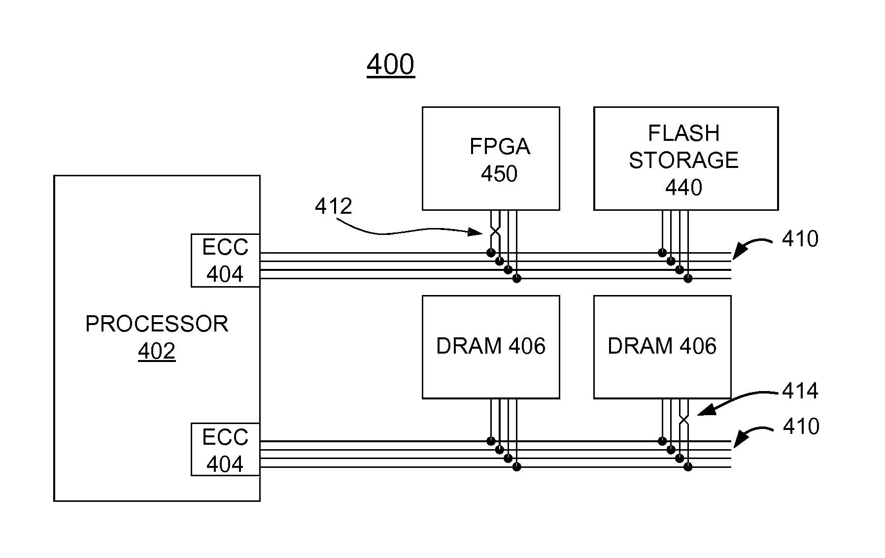
FIELD OF THE INVENTION[0001]The present invention relates generally to the data processing field, and more particularly, relates to a method, system and computer program product for implementing attachment of user mode foreign devices to a processor memory channel in a computer system.[0002]2. Description of the Related Art[0003]In a state of the art computer system, a processor memory channel is normally reserved for attaching only Dynamic Random Access Memory (DRAM) devices and user mode foreign devices are attached to an Input / Output (I / O) channel that is attached to the processor via an I / O adapter or I / O bridge. Here, the term “user mode” refers to non-privileged software applications, that is other than system software such as operating systems which are in charge of managing the hardware. The term foreign device refers to I / O peripherals originally not part of the computer system, but may be later attached to the computer system through one of the I / O channels such as the PCI...

Claims


Application Information

Patent Timeline
Patent Type & Authority Applications(United States)
IPC IPC(8): G06F12/06
CPCG06F12/06G06F12/10G06F11/1004G06F11/1008G06F12/1081G06F12/145G06F2212/206
Inventor ABALI, BULENTFRANCESCHINI, MICHELE M.LASTRAS-MONTANO, LUIS A.
Owner IBM CORP
Why Eureka
Try Eureka