Fuel injection valve and fuel injection device

a technology of fuel pressure sensor and fuel injection valve, which is applied in the direction of fuel injection with sensors, liquid fuel feeders, machines/engines, etc., can solve the problems of inaccurate measurement of fuel pressure, avoid the deterioration of the measurement accuracy of the fuel pressure sensor, and facilitate the concentration of stress

Active Publication Date: 2012-10-30
DENSO CORP +1
View PDF39 Cites 16 Cited by
  • Summary
  • Abstract
  • Description
  • Claims
  • Application Information

AI Technical Summary

Benefits of technology

[0012]The branch path diverging from the high-pressure path to deliver the high-pressure fuel to the fuel pressure sensor serves to almost eliminate the flow of fuel as compared with in the high-pressure path, so that the high-pressure fuel which hardly flows in the high-pressure path is sensed by the fuel pressure sensor, thus avoiding the deterioration of the measurement accuracy of the fuel pressure sensor caused by the flow of the fuel. This enables the fuel pressure sensor to be installed in the fuel injection valve without the deterioration of the measurement accuracy.
[0013]The invention, as recited in claim 2, is characterized in that the high-pressure path has a large-diameter portion in which a sectional area of the high-pressure path is expanded, and the branch path is bifurcated from the large-diameter portion. The large-diameter portion having a greater volume produces an effect of accumulation, which enables the pressure of fuel to be measured which is reduced in a pulsation thereof causing noise. Further, the use of the invention, as recited in claim 4, enables the use of the large-diameter portion for disposing a filter to trap a foreign object in the high-pressure fuel as a large-diameter portion for achieving the effect of the accumulation.
[0014]The diverging of the branch path from the high-pressure path will facilitate the ease with which the stress concentrates on an intersection (i.e., a branching portion) of the paths in the body, thus requiring the need for ensuring the strength of the body. In the invention, as recited in claim 3, made in view of the above, the high-pressure path has the large-diameter portion in which a sectional area of the high-pressure path is expanded. The branch path is bifurcated from a small-diameter portion of the high-pressure path other than the large-diameter portion. This enhances the strength of the body as compared with when the branch path is bifurcated from the large-diameter portion.
[0018]In the case where the branch path 6ez is, as demonstrated in FIG. 4, so formed as to extend perpendicular to the high-pressure path 6bz (i.e., claim 6), the concentration of stress on the branching portions 4az and 4bz (i.e., intersections) is minimized in the body as compared with the case where the branch path 61ez is, as illustrated in FIG. 5, so formed as to be inclined to the high-pressure path 6bz (i.e., claim 7). Alternatively, in the case where the branch path 61ez is so formed as to incline to the high-pressure path 6bz, the degree of freedom of layout of the fuel pressure sensor will be improved.
[0020]If the branching portion 4az is formed to have the shape, as indicated by the dashed line 6hz in FIG. 5(b), without being chamfered, unlike the invention, as recited in claim 8, the body will have the sharp edge 4az having an acute angle which is sensitive to breakage due to the concentration of stress thereon. In contrast, the invention, as recited in claim 8, has the acute-angle portion 4az chamfered to have the shape 6gz to decrease the possibility of the breakage due to the concentration of stress thereon.
[0022]It is, as recited in claim 10, preferable that the diaphragm is a thinnest walled portion of the branch path. This increases a displacement of the diaphragm resulting from a change in the pressure.

Problems solved by technology

A fuel pressure sensor (i.e., a rail pressure sensor) installed directly in a common rail (i.e., an accumulator vessel) to measure the above change in pressure of the fuel has a difficulty in measuring the pressure of the fuel accurately because the change in pressure of fuel arising from the spraying of the fuel is absorbed within the common rail.

Method used


Image

  • Fuel injection valve and fuel injection device
  • Fuel injection valve and fuel injection device
  • Fuel injection valve and fuel injection device

Examples


first embodiment

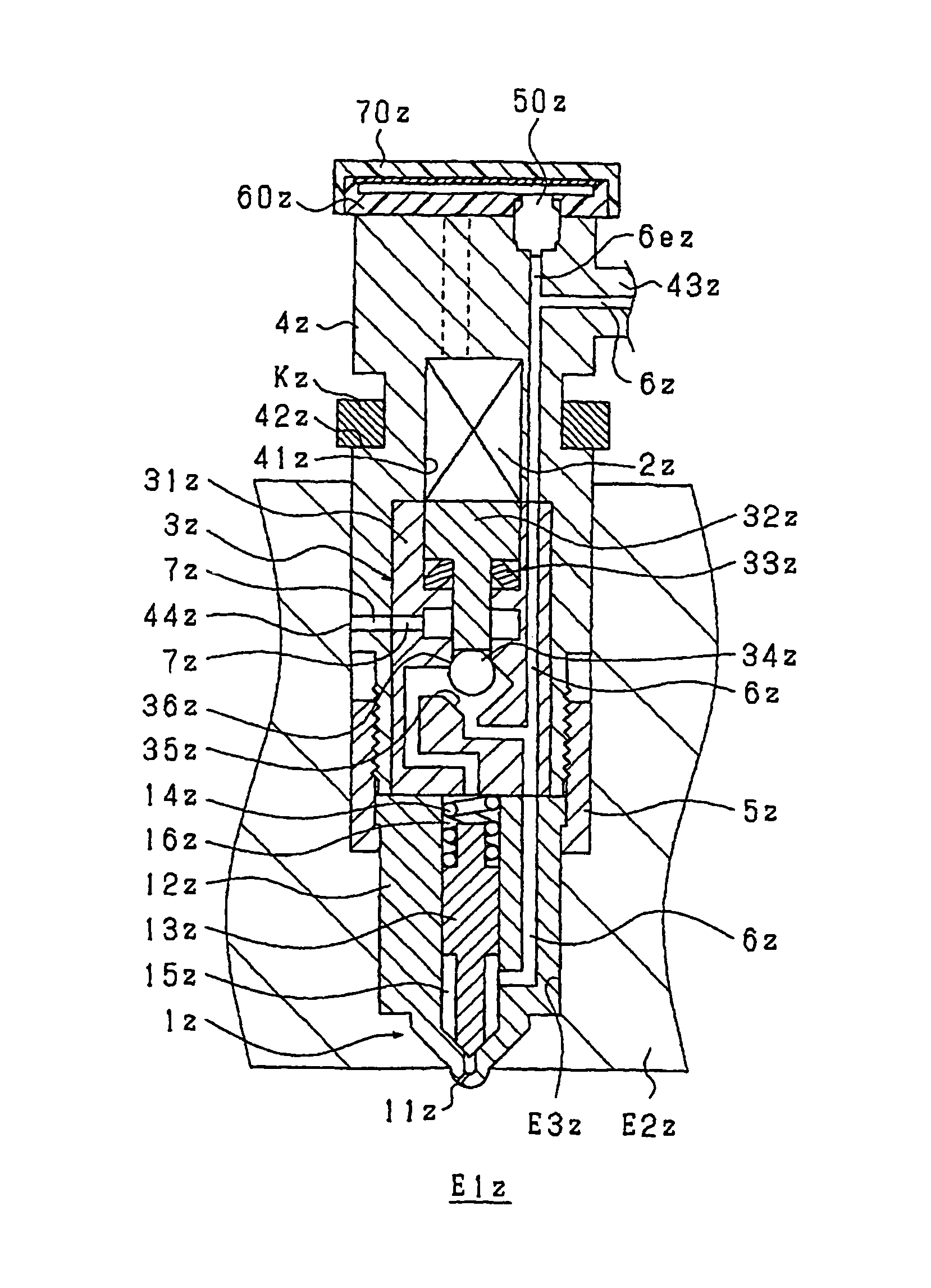
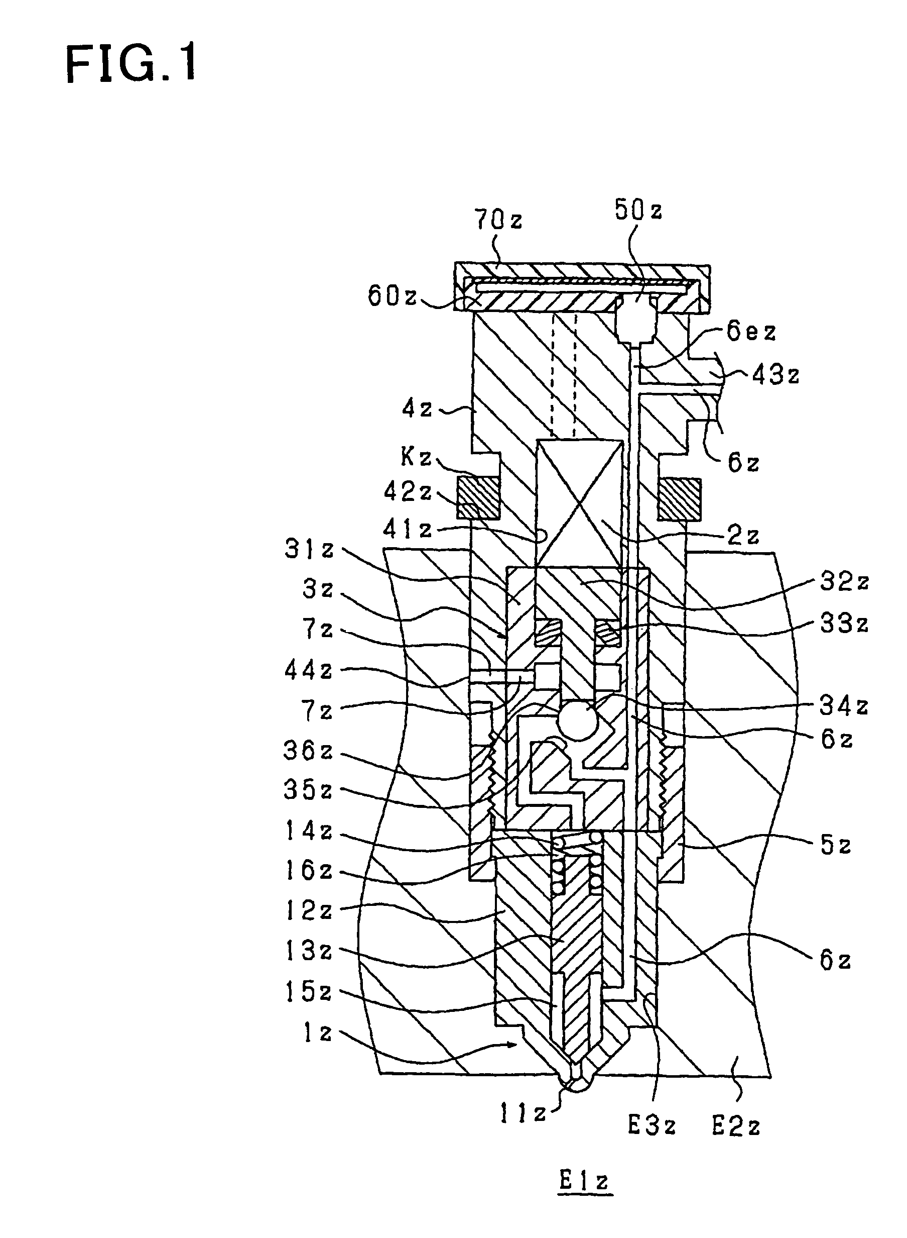
[0193]The first embodiment of the invention will be described using FIGS. 1 and 2. FIG. 1 is a schematic sectional view which shows an outline of inner structure of an injector (i.e., a fuel injection valve) according to this embodiment FIG. 2 is an enlarged view for explaining FIG. 1 in detail.

[0194]First, a basic structure and operation of the injector will be described based on FIG. 1. The injector is to spray high-pressure fuel, as stored in a common rail (not shown), into a combustion chamber E1z formed in a cylinder of an internal combustion diesel engine and includes a nozzle 1z for spraying the fuel when the valve is opened, a piezo actuator 2z (opening / closing mechanism) which expands or contracts when charged or discharged electrically, and a back pressure control mechanism 3z (opening / closing mechanism) which is driven by the piezo actuator 2z to control the back pressure acting on the nozzle 1z.

[0195]The nozzle 1z is made up of a nozzle body 12z in which spray holes 11z...

second embodiment

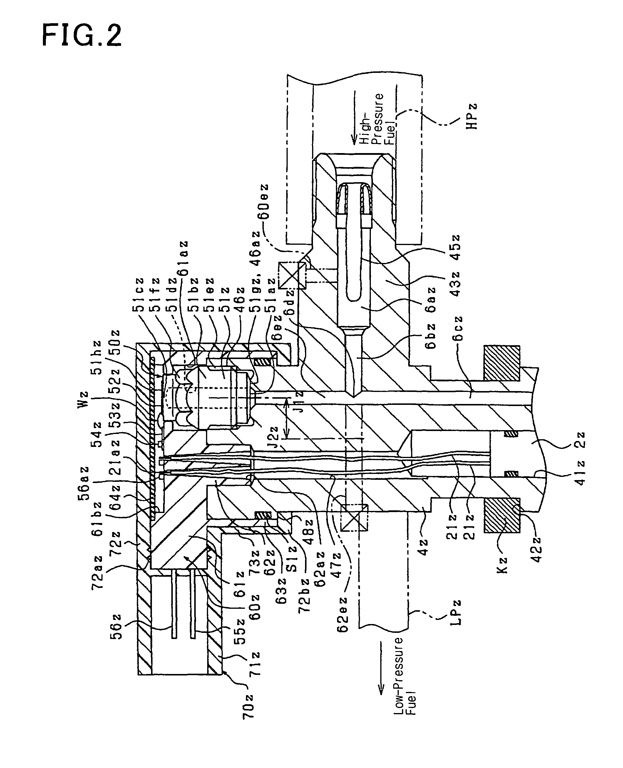
[0235]The first embodiment is so designed that the installation of the fuel pressure sensor 50z in the injector body 4z is achieved by fitting it into the injector body 4z from outside the axial line J2z of the cylindrical injector body 4z. In contrast to this, the embodiment of FIG. 3 is designed to achieve the installation from radially outside the cylindrical body 4z. Specifically, the cylindrical injector body 4z has formed in an outer circumferential surface a recess 461z into which the cylinder 51bz of the stem 51z of the fuel pressure sensor 50z is to be fitted. Therefore, a sealing surface 461az of the body 4z which creates the metal-to-metal touch seal between itself and the stem 51z is oriented so as to expand in parallel t the axial line J2z.

[0236]The high-pressure port 43z of the injector of the first embodiment is so oriented as to join the high-pressure pipe HPz in the radial direction of the injector. The high-pressure port 4311 of this embodiment is so oriented as t...

third embodiment

[0238]In the second embodiment, the branch path 6ez diverges from the large-diameter portion 6az of the high-pressure path 6z, but this embodiment of FIG. 4 has the branch path 6ez diverging from a small-diameter portion 6bz of the high-pressure path 6z.

[0239]The diverging of the branch path 6ez from the high-pressure paths 6az and 6bz facilitates the concentration of stress on a portion of the body 4z (i.e., a branching portion) where the high-pressure paths 6az and 6bz intersects with the branch path 6ez, thus requiring the need for ensuring the strength of the body 4z. This embodiment has the branch path 6ez diverging from the small-diameter portion 6bz, thus improving the strength of the branching portion of the body 4z as compared with when the branch path 6ez diverges from the large-diameter portion 6az.


PUM


Abstract

It is equipped with an injector body 4z which has formed therein high-pressure paths 6az, 6bz, and 6cz through which high-pressure fuel flows to a spray hole and stores therein a piezo-actuator 2z (i.e., an opening / closing mechanism) and a back-pressure control mechanism 3z (i.e., an opening / closing mechanism) which open or close the spray hole, and a fuel pressure sensor 50z installed in the body 4z to measure the pressure of the high-pressure fuel. The body 4z has formed therein a branch path 6ez diverging from the high-pressure paths 6bz and 6cz to deliver the high-pressure fuel to the fuel pressure sensor 50z.

Description

[0001]This application is the U.S. National Phase of International Application No. PCT / JP2008 / 069420, filed 27 Oct. 2008, which designated the U.S. and claims priority to Japanese Application No. (s) 2007-286520, filed 2 Nov. 2007, 2007-289073, filed 6 Nov. 2007, 2008-037846, filed 19 Feb. 2008 and 2008-239745, filed 18 Sep. 2008, the entire contents of each of which are hereby incorporated by reference.TECHNICAL FIELD[0002]The present invention relates generally to a fuel injection valve which is installed in an internal combustion engine to spray fuel from a spray hole and a fuel injection device.BACKGROUND ART[0003]In order to ensure the accuracy in controlling output torque of internal combustion engines and the quantity of exhaust emissions therefrom, it is essential to control a fuel injection mode such as the quantity of fuel to be sprayed from a fuel injection valve or the injection timing at which the fuel injection valve starts to spray the fuel. Accordingly, there have be...

Claims


Application Information

Patent Timeline
Patent Type & Authority Patents(United States)
IPC IPC(8): F02M51/00F02M51/06
CPCF02M47/027F02M63/023F02M57/005F02M51/005F02M2200/24F02M63/0026
Inventor KONDO, JUNTAGUCHI, TOORUARIKAWA, FUMIAKIUEDA, DAIJIYAMANAKA, AKITOSHI
Owner DENSO CORP
Why Eureka
Try Eureka