Claw for a container transporting system

a container transport system and clamp technology, applied in the direction of transportation and packaging, manufacturing tools, liquid handling, etc., can solve the problems of shortening the service life of the spring which can be mechanically damaged, affecting the functional capacity of the clamp grip, and reducing the service life of the spring, so as to achieve the effect of high repelling force and sufficient space for installation

Active Publication Date: 2012-10-30
KRONES AG
View PDF22 Cites 23 Cited by
  • Summary
  • Abstract
  • Description
  • Claims
  • Application Information

AI Technical Summary

Benefits of technology

[0008]The mutually repelling permanent magnets in the energy storage unit act as virtual springs without physical connection, where the spring characteristic can be predetermined and optimized by the design of the permanent magnets. The force is generated without any detectable abrupt separation, i.e., when the permanent magnets move away from each other, the repelling force decreases in accordance to the spring characteristic from a maximum which corresponds to the maximum closeness between the permanent magnets. This constitutes an optimal force characteristic for clamp grips. The essential advantages of the virtual springs formed from mutually repelling permanent magnets, in the case of a clamp grip, however, are the rupture safety, the abrasion-free operation, the possibility of preventing undercuts, angles or similar shapes, which could promote the attachment of microorganisms or soiling, and the insensitivity to aggressive cleaning media, combined with a minimal space requirement. Cost effective permanent magnets are available in a great variety of specifications and shapes with high production capacity, which is important for clamp grips because a very large number of clamp grips, for example, 300 or more, may be used in a container transport system.
[0022]To be able to use the clamp grips to grip the containers reliably, in cases where the dimensions of the containers may present deviations, it is advantageous to provide, between the extensions and the control cam, compensation compression spring pads and / or compensation leaf spring elements. The overall concept, as a result, has the advantage of forming a springy prestressed system without tolerance movements in practically any relative position of the grip arms.

Problems solved by technology

Clamp grips that are controlled purely mechanically between the release and the grip positions are known, for example, from EP 0 659 683 A. However, the cost of constructing the mechanical control is high.
Physical springs, such as spiral springs or rubber springs or similar devices, which are positioned in the vicinity of the grip area, i.e., close to the containers to be gripped, are critical with a view to microbiology and cleaning, because small soiling particles become easily deposited there, and, moreover, they are frequently susceptible to aggressive cleaning media, which shorten the service life of the spring which can be damaged mechanically at any time, and break, with the result that the functional capacity of the clamp grip is impaired or lost (high risk of damage to the containers).
Mutually attracting permanent magnets can be problematic because, if they come in contact with, or extremely close to, each other, an extremely strong force is required to loosen or separate them, which can lead to an undesired snapping movement of the clamp grip and to extremely high mechanical stress.

Method used


Image

  • Claw for a container transporting system
  • Claw for a container transporting system
  • Claw for a container transporting system

Examples


Embodiment Construction

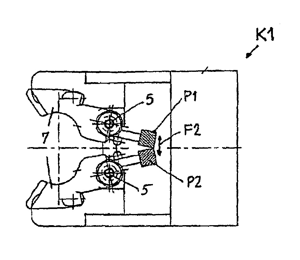
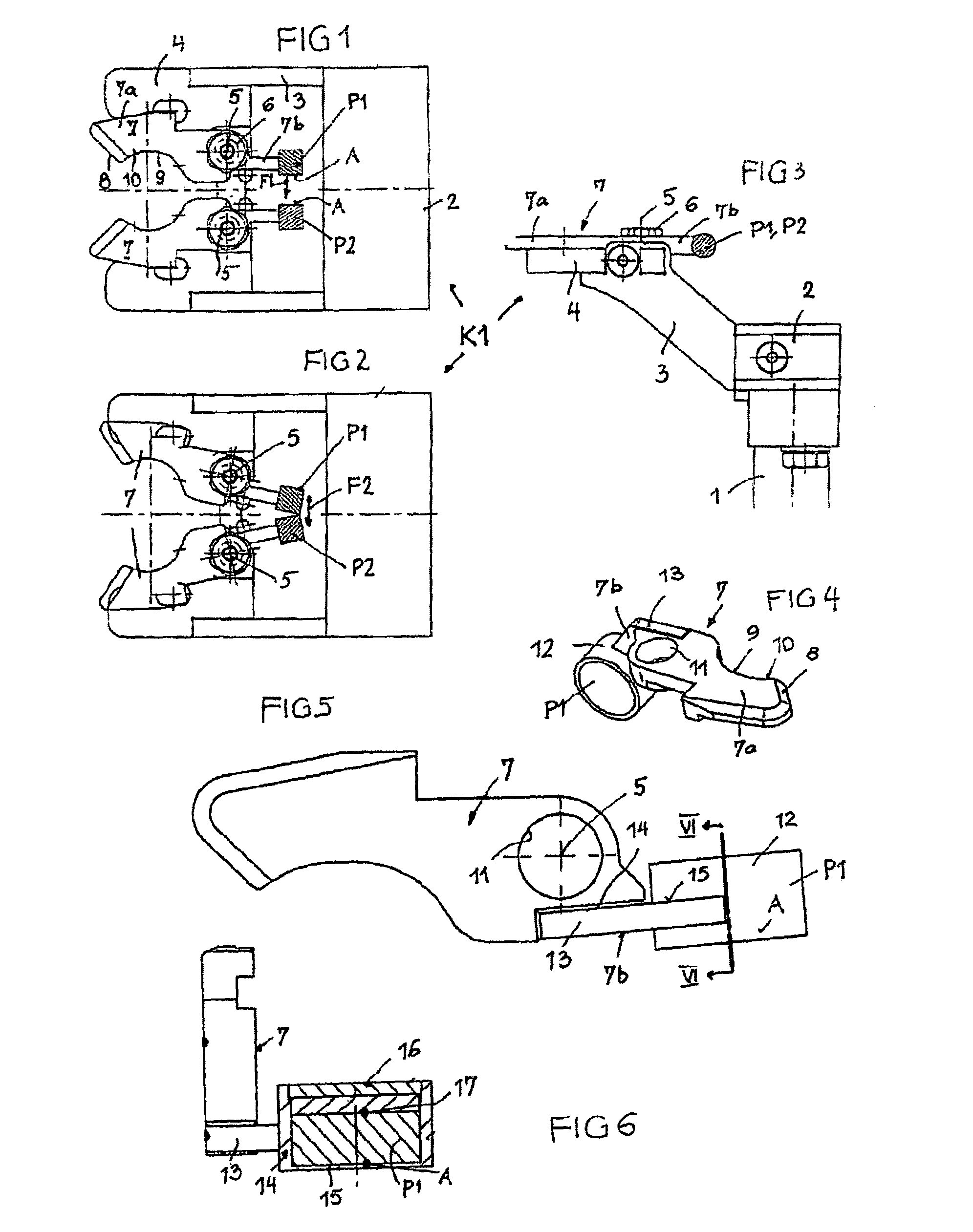
[0033]The clamp grip K1 shown in FIGS. 1-3 is an uncontrolled clamp grip, which is opened by the introduction and removal movement of a container, which is not shown, and which assumes its grip position automatically, without requiring any action on it from outside.

[0034]The clamp grip K1 is supported by a support structure 1 and an optionally swivelable support 2 with an inclined bracket 3, on which a support plate 4 sits. The clamp grip K1 presents two grip arms 7, which are substantially mirror images of each other, and which, in this embodiment, can be swiveled in opposite directions about two separate axles 5, which are fixed, for example, with screws 6, and where the swivel movement is substantially parallel to the plane of the top side of the support plate 4.

[0035]Each grip arm has a front grip part 7a with a grip recess 9, a front-side inclined introduction surface 8 and an inclined delivery surface 10. The grip arms 7 are equipped past the axles 5 with rigid extensions 7b. ...


PUM


Abstract

A clamp grip for a container transport system including rare earth permanent magnets encapsulated in non-magnetic material such as high quality steel. Flexible positioning of the magnets allow for adapting to varied design specifications. A rotatable control cam or cams may be used to adjust grip arms between a grip and a release position. Air gap distances between permanent magnets may be designed to maximize repelling force to assist in the functioning of clamp grip mechanism.

Description

CROSS-REFERENCE TO RELATED APPLICATION[0001]The present application claims the benefit of priority of International Patent Application No. PCT / EP2006 / 00618 filed on Jan. 25, 2006, which application claims priority of German Patent Application No. 20 2005 002 924.6 filed Feb. 23, 2005. The entire text of the priority application is incorporated herein by reference in its entirety.FIELD OF THE DISCLOSURE[0002]The disclosure relates to a clamp grip for a container transport system, such as a bottle transport system used in bottling operations.BACKGROUND OF THE DISCLOSURE[0003]Clamp grips that are controlled purely mechanically between the release and the grip positions are known, for example, from EP 0 659 683 A. However, the cost of constructing the mechanical control is high.[0004]From DE 297 13 510 U, mechanically controlled clamp grips are known, and also uncontrolled clamp grips which are then actuated by the containers themselves. The energy storage unit consists, for example, of...

Claims


Application Information

Patent Timeline
Patent Type & Authority Patents(United States)
IPC IPC(8): B66C1/42B65G47/84B67C3/24
CPCB65G47/847B67C3/242B65G2201/0247
Inventor KNIELING, ERWINNEUMAYER, WALTER
Owner KRONES AG
Why Eureka
Try Eureka