Method of manufacturing a three-dimensional object

a three-dimensional object and manufacturing method technology, applied in the direction of additive manufacturing, instruments, electrical equipment, etc., can solve the problems of high dependence on the power of the laser for short and long periods, simple closed loop control, and inability to achieve a stable laser power for a long period

Active Publication Date: 2012-11-06
EOS ELECTRO OPTICAL SYST
View PDF20 Cites 63 Cited by
  • Summary
  • Abstract
  • Description
  • Claims
  • Application Information

AI Technical Summary

Benefits of technology

[0016]In particular, the method has the advantage that the input control signal of the laser can be adjusted by automatic evaluation of the laser power in a very short delay and that switch-on effects can be avoided by specific switch-on ramps. In this way, deviations of the laser power in a range of 10 μs can be compensated for.

Problems solved by technology

In particular in gas lasers such as CO2-lasers, there is a problem that deviations of the power of the laser for short and long periods highly depend on the previous conditions of the laser operation, which are continuously changed.
A simple closed loop control as performed in EP-1 705 616 A1 is, however, not suitable to achieve a stable laser power for a long period.

Method used


Image

  • Method of manufacturing a three-dimensional object
  • Method of manufacturing a three-dimensional object
  • Method of manufacturing a three-dimensional object

Examples


Embodiment Construction

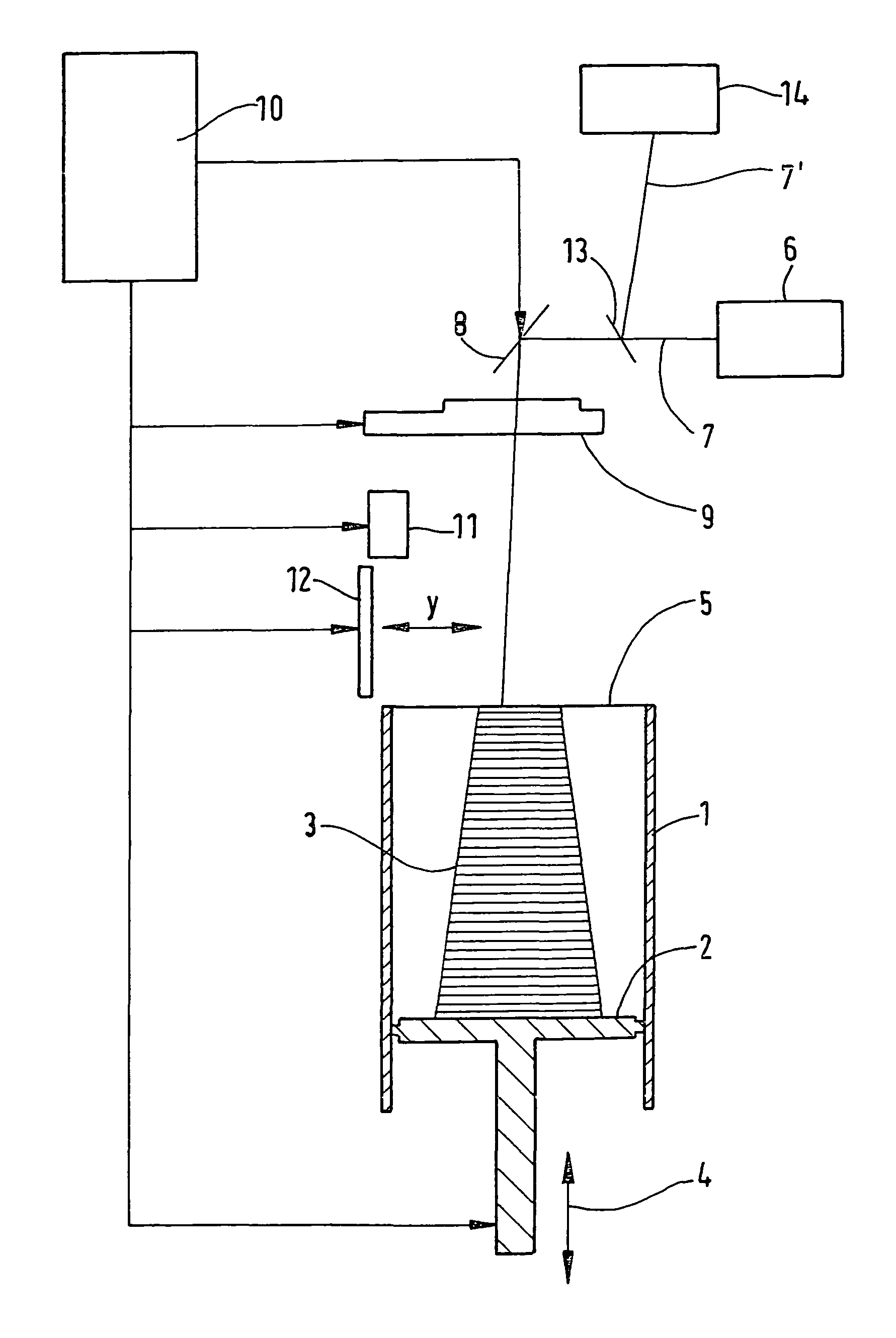
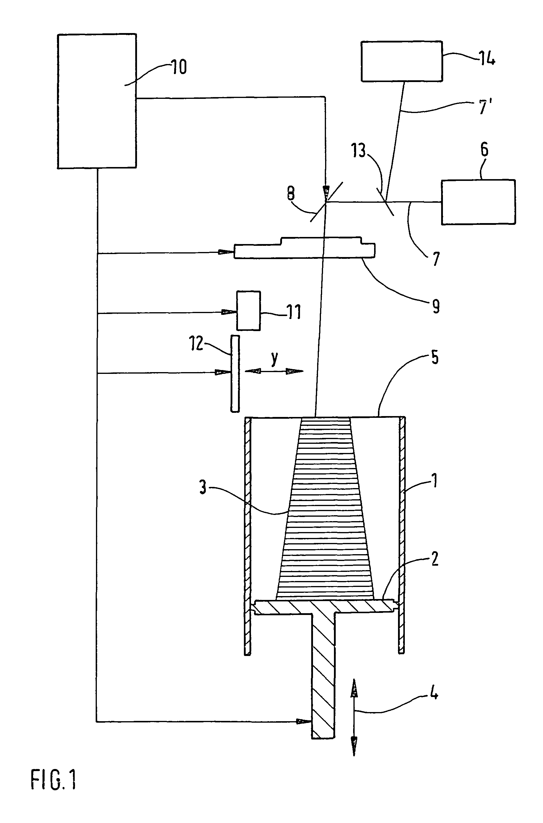
[0022]In the following, a laser sintering device having the laser control according to the invention is described with reference to FIG. 1.

[0023]The device comprises a building container 1, in which a support 2 for supporting of an object 3 to be built is provided. The support 2 is movable in a vertical direction within the building container by a height adjusting means 4. The plane, in which the applied powder building material is solidified, defines a working plane 5. For solidifying the powder material within the working plane 5, a laser 6 is provided, which can be formed as a gas laser such as a CO2-laser. The laser 6 generates a laser beam 7, which is focussed by a deflection means 8, for example in the shape of one or more deflection mirrors rotated by a rotation unit (not shown), and a focussing unit 9 onto the working plane 5. A control 10 is provided for controlling the deflection means 8 and, if necessary, the focussing unit 10 such that the laser beam 7 can be deflected t...


PUM

PropertyMeasurementUnit
transparentaaaaaaaaaa
time resolutionaaaaaaaaaa
poweraaaaaaaaaa

Abstract

A method of manufacturing a three-dimensional object is disclosed, in which the object is solidified layer by layer by solidifying a building material by means of a beam of a gas laser at locations in each layer corresponding to the cross section of the object, wherein the power of the laser is measured and the power of the laser is controlled according to the measured value. The power measurement takes place in a time window, in which a change of the power occurs, and an input control signal of the laser is controlled according to the measured values.

Description

FIELD OF THE INVENTION[0001]The invention relates to a method of manufacturing a three-dimensional object, in which the object is solidified layer by layer by solidifying a building material by means of a beam of a gas laser at locations in the layer corresponding to the cross section of the object, wherein the power of the laser is measured and the power of the laser is controlled according to the measured value.[0002]EP-0 758 952 B1 discloses a method of manufacturing a three-dimensional object by means of laser sintering, wherein the position, the power and / or the diameter of the laser beam at a location direct above the layer is measured, which is to be solidified, and wherein the result of the measurement is compared with predetermined reference values, and on the basis of the comparison, an error is displayed or the beam is corrected. Preferably, a solid state laser is used in the method.[0003]EP-1 705 616 A1 discloses a method that relates to a control of the laser power in a...

Claims


Application Information

Patent Timeline
Patent Type & Authority Patents(United States)
IPC IPC(8): B29C35/08H05B6/00G01B15/00
CPCB29C67/0066B29C64/135B33Y10/00B33Y30/00
Inventor PHILIPPI, JOCHEN
Owner EOS ELECTRO OPTICAL SYST
Why Eureka
Try Eureka