Toner recovery machine and image forming apparatus

a technology of toner recovery machine and image forming apparatus, which is applied in the direction of electrographic process apparatus, instruments, optics, etc., can solve the problems of reducing the capacity of the waste toner container, the quantity of waste toner that can be accommodated in the waste toner container decreases, and the difficulty of increasing the filling ratio of waste toner in the waste toner container, so as to increase the filling ratio of the waste toner and reduce the thickness of the container. ,

Active Publication Date: 2012-11-06
BROTHER KOGYO KK
View PDF5 Cites 0 Cited by
  • Summary
  • Abstract
  • Description
  • Claims
  • Application Information

AI Technical Summary

Benefits of technology

[0010]The exemplary embodiments of the present invention was developed in view of the above-described situations, and it is therefore an object of the exemplary embodiments to provide a toner recovery machine capable of achieving downsizing and thinning as the entire unit while increasing the filling ratio of waste toner accommodated in a waste toner container.
[0014]In this situation, since the second conveyer is provided in the container so that the sum of the radius of the first roller and the radius defined by the second conveyer is smaller than a distance in the second direction between the first axis and the second axis, the container can accommodate the waste toner up to a space under the first roller, that is, a space under the first roller, and up to the vicinity thereof. Therefore, as compared to the related toner recovery machine, it is facile to increase the filling ratio of the container. Also, for the virtue of the above positioning relationship between the first roller and the second conveyer, the second conveyer can be positioned in the container independently from the first roller without any spatial limitation. Therefore, it is possible to reduce the thickness of the container.
[0015]Thus, according to the first aspect of the exemplary embodiments of the present invention achieves to increase the filling ratio of the waste toner in the container. Also the first aspect achieves downsizing of the container and reduce the thickness of the container.

Problems solved by technology

In addition, if the toner recovery machine is thoughtlessly downsized and thinned, this brings about a decrease in capacity of the waste toner container.
Therefore, it is not possible to accommodate waste toner up to a space under the cleaning roller or the upstream side in the first pile-up direction in the waste toner container, wherein it is difficult to increase the filling ratio of waste toner accommodated in the waste toner container.
In this case, if the toner recovery machine is downsized and thinned, the quantity of waste toner that can be accommodated in the waste toner container decreases, and as a result, there is a fear that time and labor required for a user to replace a toner recovery machine and maintenance costs are increased.
Therefore, as compared to the related toner recovery machine, it is facile to increase the filling ratio of the container.

Method used


Image

  • Toner recovery machine and image forming apparatus
  • Toner recovery machine and image forming apparatus
  • Toner recovery machine and image forming apparatus

Examples


Embodiment Construction

[0030]Hereinafter, a description is given of an embodiment being an example of a detailed configuration of the present invention with reference to the drawings.

Exemplary Embodiment

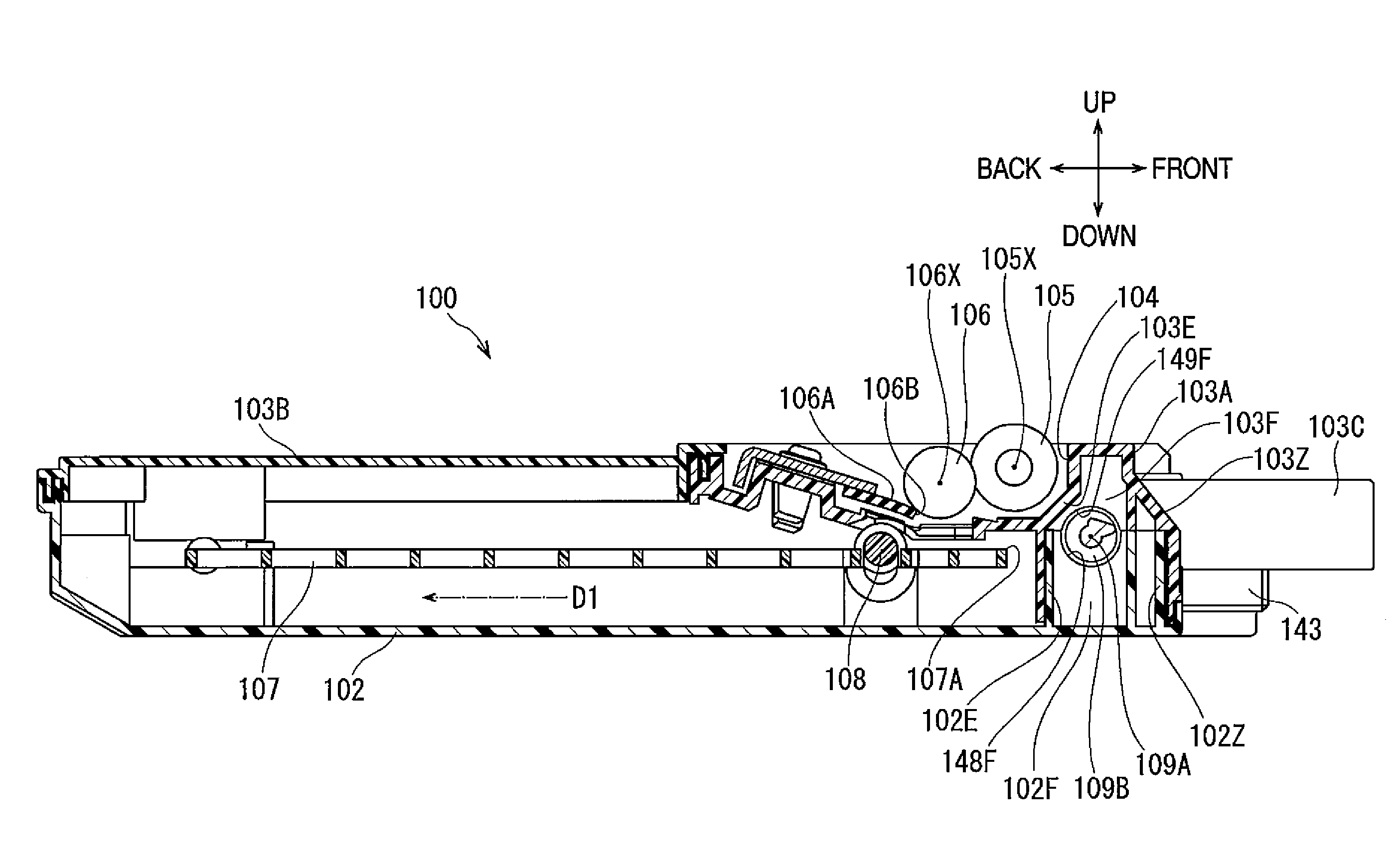
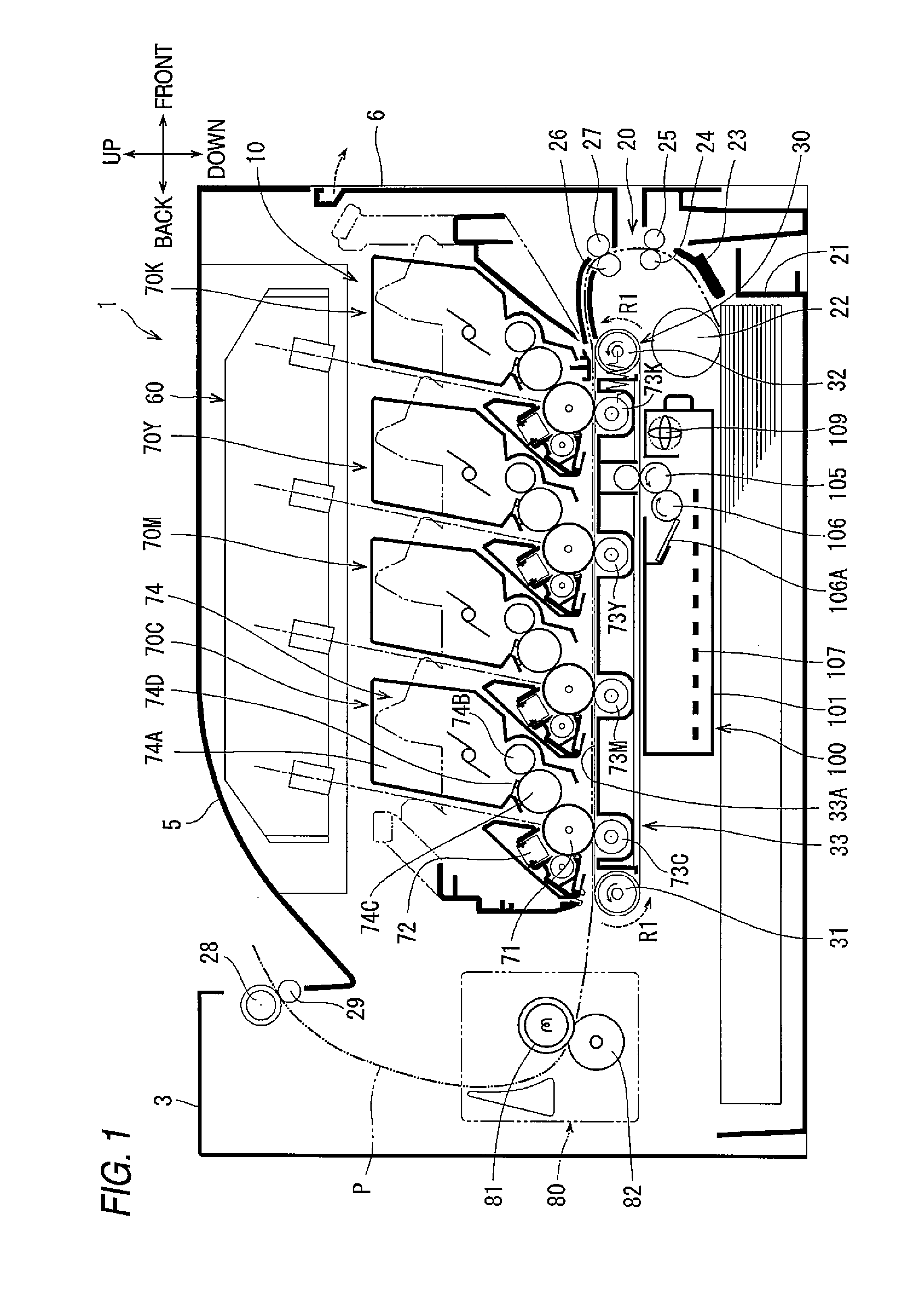
[0031]As shown in FIG. 1, a toner recovery machine 100 according to the embodiment is applied to a printer 1 that is one example of an image forming apparatus. The printer 1 is a color laser printer that forms images consisting of a plurality of colors on a sheet (including an OHP sheet, etc.) being a medium to be recorded, by means of an electro-photographic system. In FIG. 1, it is assumed that the right side of the paper is the front side of the apparatus, and the left side thereof is the rear side of the apparatus, and it is assumed that the side (this side of the paper) appearing leftward when being observed from the front side of the apparatus is the left side, and the opposite side thereof is the right side. Respective directions of the front, rear, right, left, up and down are expressed under this ...


PUM


Abstract

A toner recovery machine comprising: a first roller having a radius and rotatable about a first axis, the first axis along a first direction; a cleaner touching the first roller; a container for accommodating toner, the container comprising: a first conveyer movable along a second direction perpendicular to the first direction; and a second conveyer rotatable about a second axis and having a radius defined by the rotation about the second axis, the second axis along the first direction, wherein the second conveyer, the first roller, and the first conveyer are positioned in this order along the second direction, wherein the sum of the radius of the first roller and the radius defined by the second conveyer is smaller than a distance in the second direction between the first axis and the second axis.

Description

CROSS REFERENCE TO RELATED APPLICATIONS[0001]The present application claims priority form Japanese Patent Application No. JP-2009-129557 filed on May 28, 2009, and the subject matter of which is incorporated herein by reference.TECHNICAL FIELD[0002]The present invention relates to a toner recovery machine and an image forming apparatus.BACKGROUND[0003]A toner recovery machine of related art is arranged with an offset belt. The offset belt acts as a toner carrier that circulates while directly carrying toner on the surface of a recording medium on which an image has already been formed. The toner recovery machine includes a cleaning roller, a waste toner container, first conveyer and second conveyer.[0004]The cleaning roller has a first rotation shaft orthogonal to the circulation direction of the offset belt. The cleaning roller rotates around the first rotation shaft and recovers waste toner carried on the offset belt on the surface thereof. The waste toner container supports the f...

Claims


Application Information

Patent Timeline
Patent Type & Authority Patents(United States)
IPC IPC(8): G03G15/16
CPCG03G21/105
Inventor TSUSAKA, SHUSAKUKAWAHARA, EIJITSUKADA, TAKAMASA
Owner BROTHER KOGYO KK
Why Eureka
Try Eureka