Absolute optical encoder with long range intensity modulation on scale

an optical encoder and scale technology, applied in the field of precision measurement instruments, can solve the problem of limiting the absolute maximum measurement range of the encoder to less than desired for a number of applications, and achieve the effect of increasing the range-to-resolution ratio, without increasing the overall scale width

Active Publication Date: 2012-11-13
MITUTOYO CORP
View PDF43 Cites 75 Cited by
  • Summary
  • Abstract
  • Description
  • Claims
  • Application Information

AI Technical Summary

Benefits of technology

[0010]The present invention is directed to improved absolute encoder configurations that provide improved combinations of range-to-resolution ratio, high resolution, longer range, compact size, robustness, and fabrication and assembly cost.
[0014]In contrast to known methods of providing a longer absolute measurement range by adding additional scale tracks, the present invention provides a longer absolute measurement range without adding an additional scale track by providing at least one scale track including a DMST pattern according to principles disclosed herein, which provides a first intensity modulation component that has a first spatial wavelength SW1 and repeats a plurality of times over the measuring range (e.g., producing a medium wavelength signal), and also provides a second intensity modulation component that varies at a slower rate than the first intensity modulation component along the measuring axis direction, and / or that may have a unique value at each point within the measuring range (e.g., producing a long-range absolute measurement signal). The second intensity modulation component is detected in order to provide a more slowly varying signal which functions similarly to the longer spatial wavelength signals provided by additional absolute tracks in prior art designs. The net result is that a higher range-to-resolution ratio is achieved with reasonable interpolation levels and without increasing the overall scale width.

Problems solved by technology

The maximum length of the synthetic wavelength that can be practically achieved using the scale track patterns disclosed in the '813 patent still places a limit on the maximum absolute measuring range of the encoder that is less than desired for a number of applications.

Method used


Image

  • Absolute optical encoder with long range intensity modulation on scale
  • Absolute optical encoder with long range intensity modulation on scale
  • Absolute optical encoder with long range intensity modulation on scale

Examples


Embodiment Construction

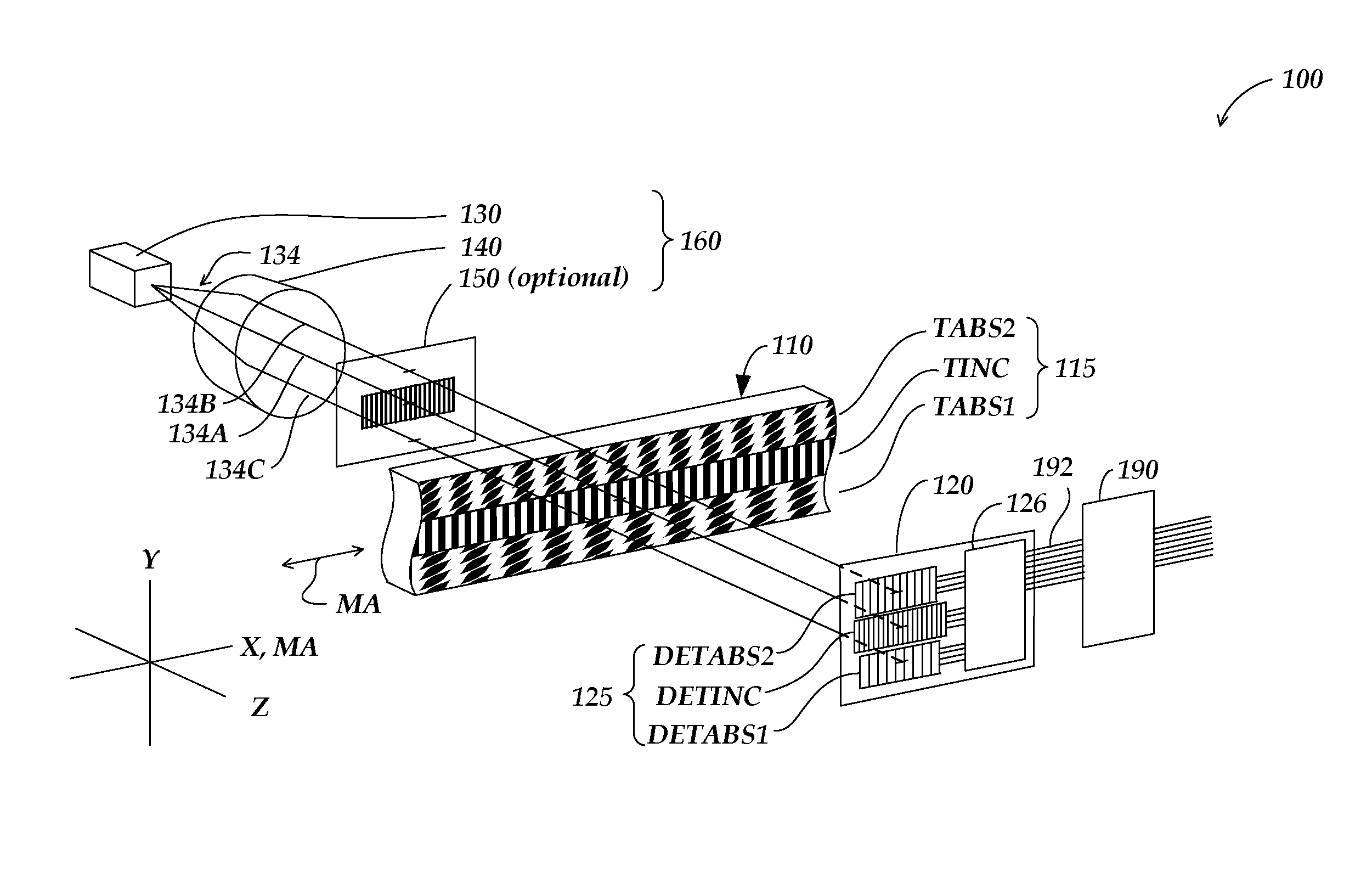
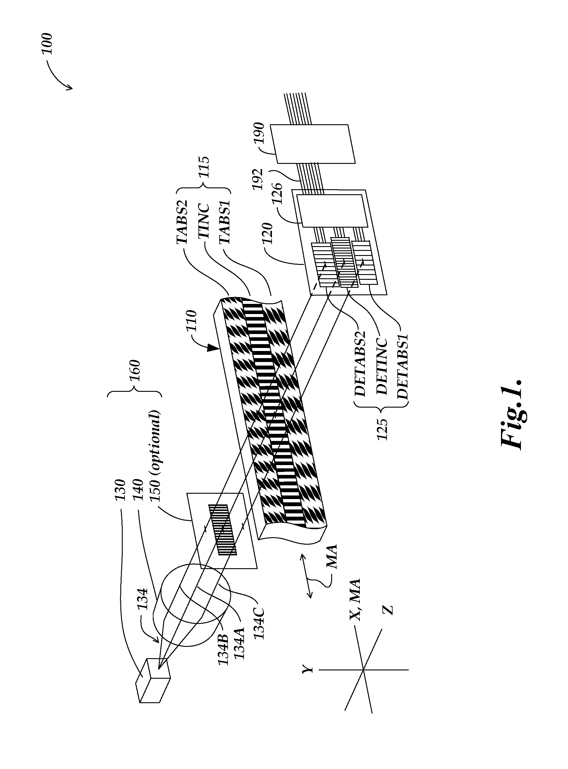
[0030]FIG. 1 is an exploded diagram schematically illustrating one embodiment of an absolute optical encoder configuration 100 that can employ the dual-modulation scale track pattern features and detector configurations disclosed herein. Certain aspects of the encoder configuration 100 are described in more detail in the previously incorporated '813 patent. As shown in FIG. 1, the encoder configuration 100 includes a scale element 110, detector electronics 120 which are connected to signal generating and processing circuitry 190 by power and signal connections 192, and an illumination system or portion 160 comprising a light source 130 for emitting visible or invisible wavelengths of light, a lens 140, and an optional source grating 150. The light source 130 may also be connected to the signal generating and processing circuitry 190 by power and signal connections (not shown). The scale element 110 includes an absolute scale pattern 115 including three scale track patterns—an increm...


PUM


Abstract

An encoder configuration comprises a dual-modulation scale track pattern that provides a first intensity modulation component for producing periodic signals, and a second intensity modulation component for producing a long-range absolute signal. The dual-modulation scale track pattern increases the range-to-resolution ratio of the encoder without the use of additional scale tracks that would increase the width of the encoder components. The long-range signal may be encoded in the dual-modulation scale track pattern either by varying certain dimensions of pattern elements included in the scale track or by superimposing a layer including an optical density variation along on the track on pattern elements of similar areas. In either case, the net offset and / or amplitude levels of the associated signals are modified along the scale track. These modified offset and / or amplitude levels provide the basis for the long-range absolute signal.

Description

FIELD OF THE INVENTION[0001]The invention relates generally to precision measurement instruments, and more particularly to an absolute optical encoder configuration with a long-range intensity modulation on the scale.BACKGROUND OF THE INVENTION[0002]Incremental position encoders utilize a scale structure that allows the displacement of a readhead relative to a scale to be determined by accumulating incremental units of displacement, starting from an initial point along the scale. Such encoders are suitable for certain applications, particularly those where line power is available. However, in certain applications, such as those where encoders are used in low power consumption devices, it is more desirable to use absolute position encoders. Absolute position encoders provide a unique output signal, or combination of signals, at each position along a scale. They do not require continuous accumulation of incremental displacements in order to identify a position. Thus, absolute position...

Claims


Application Information

Patent Timeline
Patent Type & Authority Patents(United States)
IPC IPC(8): G01D5/34G01B11/14
CPCG01D5/24476G01D5/2448G01D5/34784
Inventor KAPNER, DANIEL JOHNMILVICH, MICHELLE MARY
Owner MITUTOYO CORP
Why Eureka
Try Eureka