Scale track configuration for absolute optical encoder including a detector electronics with plurality of track detector portions

a technology of absolute optical encoder and detector electronics, applied in the direction of converting sensor output optically, instruments, measurement devices, etc., can solve the problems of significant fabrication, detection and signal processing problems, and is not suitable for a practical high-resolution absolute encoder, and achieve the best range-to-resolution ratio, the effect of reducing the fidelity of sinusoidal signals and achieving the best possible sinusoidal fidelity

Active Publication Date: 2009-10-27
MITUTOYO CORP
View PDF29 Cites 105 Cited by
  • Summary
  • Abstract
  • Description
  • Claims
  • Application Information

AI Technical Summary

Benefits of technology

[0010]The present invention is directed to improved absolute encoder configurations that provide improved combinations of range-to-resolution ratio, high resolution, compact size, robustness, and fabrication and assembly cost.
[0013]It should be appreciated that, generally speaking, sinusoidal output signals are used for signal interpolation in encoders due to some desirable signal processing advantages. However, sinusoidal signal fidelity may be lowered by optical noise (e.g., stray light, non-uniform light, or unwanted diffraction effects), electronic noise, inaccurate patterns or alignment or relative motion (e.g., motion or misalignment along the Y axis), and spatial harmonic signal components (e.g., a square wave pattern passing a linear detector produces a trapezoidal illuminated area variation as a function of position, which includes significant spatial harmonic content.) Several advantageous signal interpolation methods (e.g., well-known quadrature signal interpolation methods) assume ideal sinusoidal signals, and loss of sinusoidal fidelity directly affects their interpolation accuracy and the resulting interpolation ratio. Thus, in order to reliably provide an absolute encoder with the best range-to-resolution ratio possible, in as small a size as possible (e.g., by using very few absolute tracks), it is essential to maintain the best possible sinusoidal fidelity under all expected misalignments and operating variations. Among other advantages, the inventive configurations outlined below provide significant improvements in sinusoidal fidelity in comparison to the techniques described in the prior art, particularly with respect to providing robust and accurate operation under various misalignments and operating variations that may be expected in a practical and economical device. The inventive configurations may provide particularly economical and compact devices with an excellent range to resolution ratio.
[0014]In various embodiments according to this invention an encoder configuration for use in an absolute position sensing device comprises an illumination portion, a scale element including an absolute scale pattern comprising a fine track pattern and at least a first absolute track pattern, and the detector electronics. The various track patterns are arranged to receive light from the illumination portion and output respective spatially modulated light patterns along respective light paths to various corresponding detector portions of the detector electronics (e.g., a fine track detector portion and at least a first absolute track detector). The fine track pattern and its corresponding detector portion may be configured according to known techniques. In various embodiments an absolute track detector portion may be configured with individual photodetector areas that have a Y direction edge-to-edge dimension YDETABS along a Y direction that is perpendicular to a measuring axis direction, and these photodetector areas may be configured to spatially filter their received spatially modulated light pattern and output a plurality of respective position indicating signals that have respective spatial phases. In accordance with one aspect of this invention, an absolute track pattern comprises geometrically congruent subtrack portions that extend along the measuring axis direction, and the geometrically congruent subtrack portions are arranged such that if one of the geometrically congruent portions is translated along the Y direction by the dimension YDETABS, then the geometrically congruent portions will nominally coincide. The geometrically congruent subtrack portions may furthermore be configured such that they are separated along the Y direction by a dimension YCENT that is less than YDETABS, and the geometrically congruent subtrack portions may each have a Y direction dimension YTOL, such that the dimensional quantity [YCENT+2(YTOL)] is greater than YDETABS. Thus, the detector portion for sensing the absolute track may be narrower than the absolute track pattern along the Y direction, but because the ends of the photo detectors are each nominally located over geometrically congruent sub track portions (to sense geometrically congruent light patterns), the detected signal is not sensitive to misalignment of the detector portion along the Y direction. It will be appreciated that a narrower detector portion is more economical, and may also facilitate a compact device.

Problems solved by technology

Thus, such a configuration is not suitable for a practical high resolution absolute encoder.
This raises significant fabrication, detection and signal processing issues not addressed in the '655 patent.
This is more demanding than the fabrication requirements of a typical incremental scale track, which may dramatically increase scale fabrication costs.
Secondly, such feature sizes may give rise to undesirable diffraction effects, which introduces signal noise and lowers the S / N ratio, which lowers the reliable interpolation ratio, particularly near the ends of each repeated pattern (where an abrupt feature width or density transition takes place).
Thirdly, such small feature sizes may be sensitive to blurring variations if the gap to the detector and light source is not carefully controlled.
Too much blurring will degrade the S / N ratio, and too little blurring may introduce unwanted spatial frequencies into the detected signal.
For these and other reasons, the patterns of FIGS. 1A-1C are not sophisticated enough to provide a good range-to-resolution ratio in combination with high resolution (e.g., on the order of microns, or less).
However, if this area is not provided and the end of a photo diode is located within the track pattern 200, the variation of illumination area on the detector will not be a sinusoidal function of position (e.g., the peak of the function may be truncated), so the output signal will not exhibit the desired or expected sinusoidal variation with position, which disrupts meaningful signal interpolation.

Method used


Image

  • Scale track configuration for absolute optical encoder including a detector electronics with plurality of track detector portions
  • Scale track configuration for absolute optical encoder including a detector electronics with plurality of track detector portions
  • Scale track configuration for absolute optical encoder including a detector electronics with plurality of track detector portions

Examples


Embodiment Construction

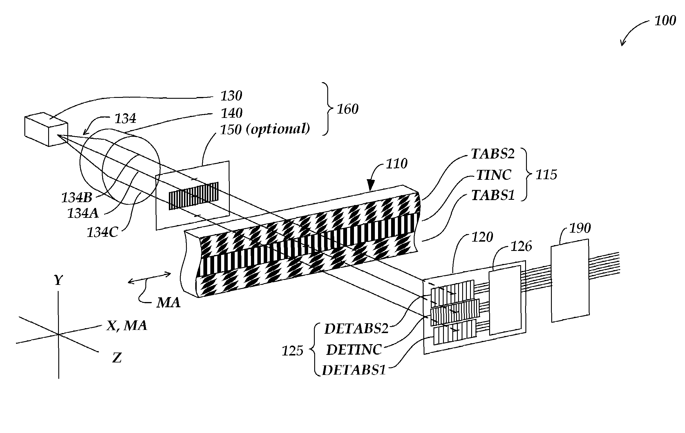
[0025]FIG. 3 is an exploded diagram schematically illustrating one embodiment of an absolute optical encoder configuration 100 including various features in accordance with the present invention. As shown in FIG. 3, the encoder configuration 100 includes a scale element 110, detector electronics 120 which is connected to signal generating and processing circuitry 190 by power and signal connections 192, and an illumination system or portion 160 comprising a light source 130 for emitting visible or invisible wavelengths of light, a lens 140, and an optional source grating 150. The light source 130 may also be connected to the signal generating and processing circuitry 190 by power and signal connections (not shown). The scale element 110 includes an absolute scale pattern 115 including three scale track patterns: an incremental track pattern TINC, a first absolute track pattern TABS1, and a second absolute track pattern TABS2, described in more detail below with reference to FIG. 4. ...


PUM


Abstract

An encoder configuration comprises an illumination portion, absolute scale pattern comprising absolute tracks, and a detector having a width dimension YDETABS. An absolute track pattern comprises geometrically congruent sub tracks, and the congruent sub tracks are arranged such that if one is translated by the width dimension YDETABS, then they will nominally coincide. The congruent sub tracks may be separated by a dimension YCENT that is less than YDETABS, and may each have a dimension YTOL, such that [YCENT+2(YTOL)] is greater than YDETABS. Thus, the detector may be narrower than the absolute track pattern, but because the detector edges are each nominally located over congruent sub tracks the detected signal is not sensitive to lateral misalignment of the detector within the pattern. These principles provide great freedom in configuring advantageous individual pattern features in the absolute track, even though the detector is narrower than the absolute track.

Description

FIELD OF THE INVENTION[0001]The invention relates generally to precision measurement instruments, and more particularly to an absolute optical encoder configuration with multiple scale tracks that may rely on multiple optical sensing principles.BACKGROUND OF THE INVENTION[0002]Incremental position encoders utilize a scale structure that allows the displacement of a readhead relative to a scale to be determined by accumulating incremental units of displacement, starting from an initial point along the scale. Such encoders are suitable for certain applications, particularly those where line power is available. However, in certain applications, such as those where encoders are used in low power consumption devices, it is more desirable to use absolute position encoders. Absolute position encoders provide a unique output signal, or combination of signals, at each position along a scale. They do not require continuous accumulation of incremental displacements in order to identify a posit...

Claims


Application Information

Patent Timeline
Patent Type & Authority Patents(United States)
IPC IPC(8): G01D5/34
CPCG01D5/34784
Inventor MILVICH, MICHELLE M.TOBIASON, JOSEPH D.
Owner MITUTOYO CORP
Why Eureka
Try Eureka