Microcontroller-based lighting control system and method for lighting control

a microcontroller and control system technology, applied in lighting devices, electroluminescent light sources, light sources, etc., can solve the problems of inability to substantially adjust the turn-on period of bi-directional control switches such as triac, inability to achieve the effect of implementing more desirable functions, and inability to easily combine structures using variable resistors to control light intensity to achieve more desirable functions

Active Publication Date: 2012-11-13
VAXCEL INT
View PDF5 Cites 44 Cited by
  • Summary
  • Abstract
  • Description
  • Claims
  • Application Information

AI Technical Summary

Benefits of technology

[0012]The present invention provides the advantage to implement the lighting control circuit functions by only one single microcontroller. In the conventional arts of lighting control it usually employs lots of discrete analog and digital integrated circuits. By comparison, the related circuit structure of the present invention is simple and the circuit assembly cost can be low. Particularly, the unit price of an eight-bit OTP microcontroller is acceptable in comparison with that of conventional analog and digital integrated circuits. Another advantage is the possibility to change lighting control schemes by simply modifying the microcontroller program codes without changing the main circuit structure. A further advantage of the present invention is to provide an effective power saving circuit system that is superior to the conventional analog-digital hybrid arts. Still further, it is another advantage that the present invention provides flexibility to design time-delay pulses with appropriate delay time lying behind the zero-crossing-point of AC power. This feature is essential for controlling lighting loads of different electric impedances, which may be incandescent lamps, fluorescent lamps or light-emitting diodes, without changing the circuit components on circuit board.

Problems solved by technology

However, since the conventional system of this art is limited by its fundamental design, the turn-on period of the bi-directional control switch (such as TRIAC) may not be substantially adjusted for transmitting a full power or a predetermined minimal power to the lighting load.
Moreover, the structure using a variable resistor to control light intensity may not be easily coupled with other electronic circuits to implement more desirable functions.
However, the above-mentioned two arts have complicated circuit assembly.
Therefore, they cause high manufacturing cost and even result in high electric power consumption.
This quantity of electric power loss is even larger than the electric power dissipated at a low brightness state of the lighting load.
Therefore, this conventional art of light control system with analog-digital hybrid circuits is not in compliance with the purpose of electric power saving.

Method used


Image

  • Microcontroller-based lighting control system and method for lighting control
  • Microcontroller-based lighting control system and method for lighting control
  • Microcontroller-based lighting control system and method for lighting control

Examples


first embodiment

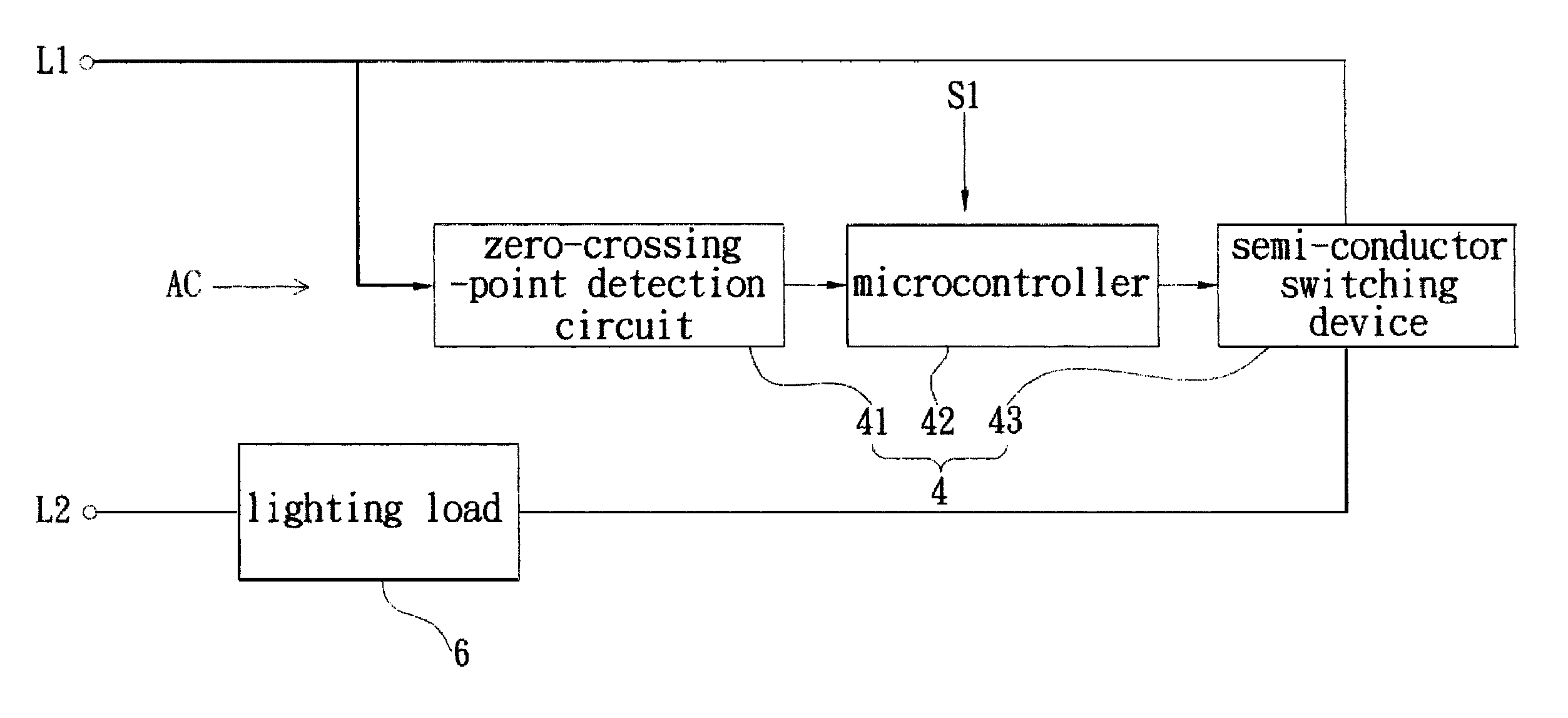
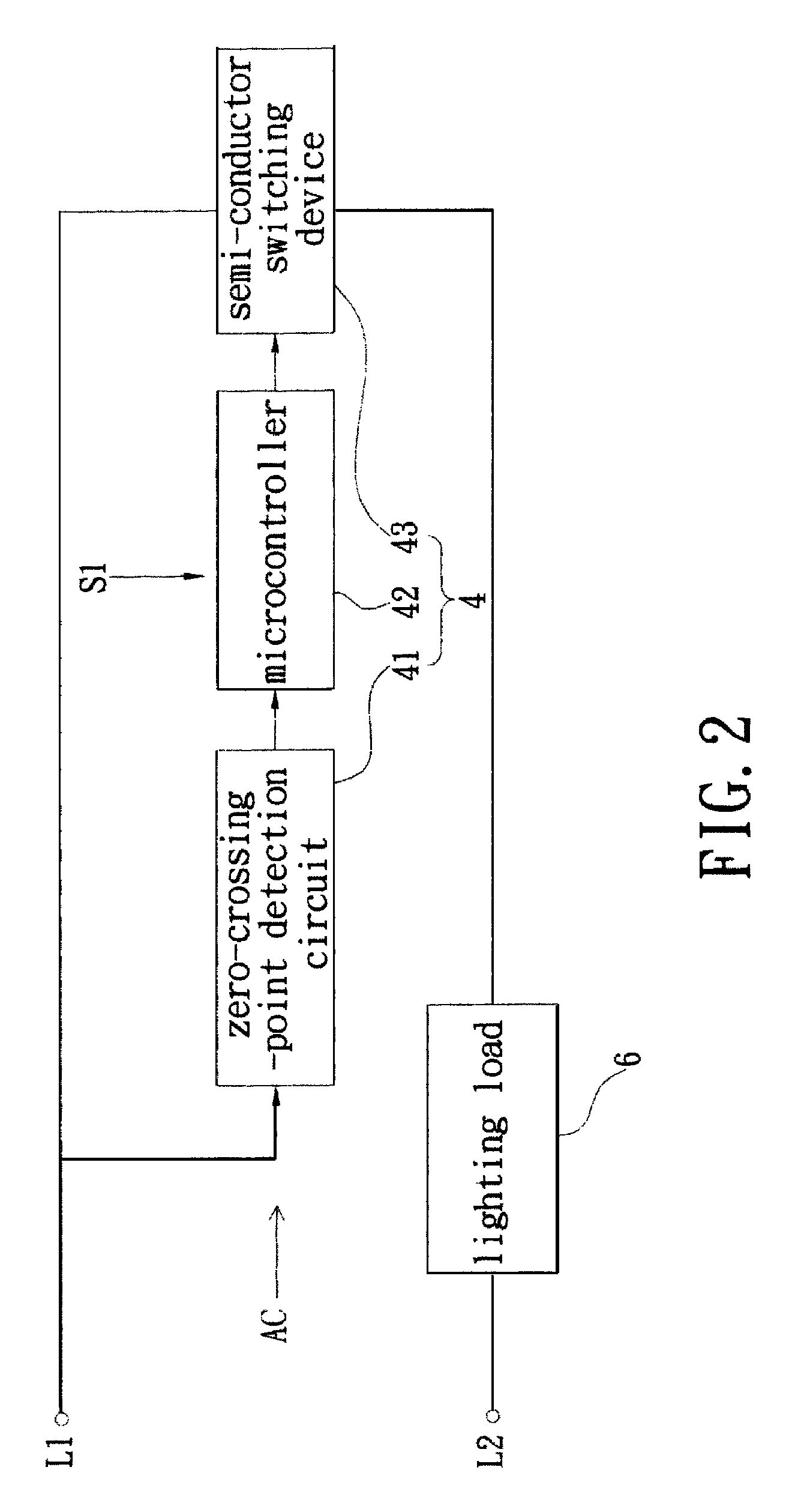
[0028]Reference is made to FIG. 2 showing a schematic diagram of a lighting control system in accordance with the present invention. The lighting control system substantially includes a zero-crossing-point detection circuit 41, a microcontroller 42, and a semi-conductor switching device 43. The components 41, 42 and 43 form a fundamental lighting control circuit 4.

[0029]Furthermore, the lighting control system is provided with an external control signal S1 which is fed by mechanical or electronic means to the microcontroller 42. Reference is made to FIG. 2. One terminal of the semi-conductor switching device 43 is connected to a wire L1 of an AC power. The other terminal of the device 43 is connected to one end of the lighting load 6, which has its other end connected to another wire L2 of the AC power. Further, the semi-conductor switching device 43 has a third terminal coupled to the microcontroller 42 for receiving trigger control signals. This type of lighting control system in ...

second embodiment

[0061]Reference is made to FIG. 8, which shows a schematic diagram of the lighting control system in accordance with It adopts an electronic means to transmit the external control signal S1 to the microcontroller 42 for selecting an external control loop. The program codes of the microcontroller 42 then executes a time-delay pulse subroutine according to a scheme of FIG. 7. After that, the zero-crossing-point time-delay pulses with different time lags tD are generated and used for controlling the turn-on period of the semi-conductor switching device 43. In FIG. 8, the microcontroller 42 is coupled to an output terminal of the detection circuit 7. This detection circuit 7 can be a motion detection circuit, a daylight detection circuit, or a sound detection circuit, or any one of their combinations.

[0062]Similar to the aforementioned mechanical means, it is appropriately to set an effective external control signal S1 as zero voltage that may be a temporary ground signal. The detectio...


PUM


Abstract

A lighting control system employs a microcontroller to generate time-delay pulses that are synchronized with the AC power. The time-delay pulses control conduction period of a semi-conductor switching device for transmitting AC power to a lighting load. This lighting control system enables the lighting load performing two-level or multi-level illumination in a simple and power saving manner. While the conventional circuits use cumbersome passive resistor-capacitor scheme to generate required timing control, this lighting control system uses simple scheme based on a built-in oscillator in the microcontroller. This scheme provides high flexibility and accuracy to implement delay-time triggering. The system and method in the present invention may simultaneously be applicable to lighting loads of different impedance types, especially to incandescent lamp, fluorescent lamp, and AC light emitting diode.

Description

BACKGROUND OF THE INVENTION[0001]1. Field of the Invention[0002]The present invention relates to a lighting control system using a microcontroller, and to a lighting control method thereof, in particular, to the lighting control system and method for transmitting various electric powers to a lighting load by the microcontroller.[0003]2. Description of Related Art[0004]Refer to FIG. 1, which shows a schematic diagram of a conventional lighting control system. This kind of lighting control system has a light-dimming circuit 2, which is used to control an AC power to deliver a specific value of electric power to a lighting load 1. The light-dimming circuit 2 further includes a semi-conductor switching device 20 and a phase triggering circuit 22. This switching device 20 may be a well-known bi-directional control switch. The phase triggering circuit 22 usually comprises a variable resistor and a capacitor to generate trigger signals with variant time differences. The trigger signals are...

Claims


Application Information

Patent Timeline
Patent Type & Authority Patents(United States)
IPC IPC(8): H05B37/02
CPCH05B33/0809H05B33/0845H05B39/083Y02B20/342H05B45/10Y02B20/30
Inventor CHEN, CHIA-TEH
Owner VAXCEL INT
Why Eureka
Try Eureka