Method for building a depositional space corresponding to a geological domain

a depositional space and domain technology, applied in the field of stratified terrain modeling, can solve the problems of inaccurate geological methods, badly-shaped (concave or zero-volume) elements, and achieve the effect of simplifying the processing of geological models

Active Publication Date: 2012-11-20
SCHLUMBERGER TECH CORP
View PDF12 Cites 28 Cited by
  • Summary
  • Abstract
  • Description
  • Claims
  • Application Information

AI Technical Summary

Benefits of technology

[0040]So the invention makes possible the computation of a depositional coordinate system (u, v, w), advantageously honoring the “P1” and “P2” properties, where the geometry of the 3D geological domain is physically reliable, thereby allowing the definition of a low-distorted computational space where measured Euclidean distances are close to geodesic distances. When applied in that depositional space, geostatistical interpolations or simulation algorithms can advantageously model the physical properties of the 3D geological domain with an improved accuracy. The generation of meshes honoring the complex geometries of geological structures can also be made much easier when performed in that depositional space. As another example, the quality of a 3D seismic reflection interpretation can be more precisely checked if run in that depositional space.
[0045]With the present invention, faults (or any other boundaries) are free to slip and deform, provided that mechanical contact is honored (“P2” property). This means that equilibrium of forces has been reached, without overlapping or penetration across the faults. The corresponding slip directions and magnitudes are thus an output of the computation instead of an input. The produced slip vectors result from a simulation that honors the fundamental principles of both fracture mechanics and physics that govern rock deformation. As a consequence, they provide a reliable physically-based geometry of the geological domain in the depositional space. The same remark applies to horizons: with a parametric method such as the one disclosed in document WO 2005 / 119304, it is not possible to model the bedding slip / detachment (or any other kind of sliding along a horizon) that might have affected some layers of the geological domain, whereas it is very easy to do so with the method according to the invention, just by setting a boundary condition that allows mechanical contact with shearing at layers interfaces.
[0046]Moreover, the present invention does not simplify the processed geological model. All the faults are taken into account, whatever the connections between them. Faults can have free borders and do not need to be artificially extended so that to be entirely connected with other boundaries of the model. The present invention is also not limited to a particular tectonic context. For example, extensional structures or compressive structures are handled exactly the same way. So the present invention can advantageously handle the full complexity of geological models.
[0057]the mechanical simulation step is not limited to the small displacement hypothesis and can handle large deformations, avoiding in that case the undesirable side effects of rotations,

Problems solved by technology

Thus, geostatistical methods produce inaccurate results if applied directly to the present-day space, described by the Cartesian coordinate system (x, y, z).
This solution suffers from several drawbacks and limitations:On one hand, most of the algorithms used for building such stratigraphic grids create badly-shaped (i.e. that is stretched, squeezed, concave or zero-volume) elements in the present-day (x, y, z) space, especially in the neighborhood of faults.
As these elements are all right cuboids, or regular parallelepipeds, in the depositional (u, v, w) space, this means that there is a distortion when mapping points from one space to another.
This distortion can be very high locally and reduces the accuracy of the property modeling.
As a consequence, there are gaps or overlaps in the depositional space.
Both situations are unacceptable, as they break the required “P2” property.
This solution suffers from several drawbacks and limitations:First of all, it falls in the category of geometric and kinematic approaches for modeling the deformation of the terrains through time.
As a consequence, the produced depositional space is inappropriate for modeling the physical properties of the geological domain if terrains are believed to deform according to another kinematic style or any other combination of kinematic styles, such as vertical shear, inclined shear, fault-parallel flow, etc. . . . Moreover, it is uncertain which kinematic style or combination of kinematic styles should be used to model the deformation of the terrains.
Indeed, kinematic methods are not based on the fundamental principles of the conservation of mass and momentum, which govern rock deformation.
This can be considered as a severe limitation, because imposed slip directions and magnitudes are not a priori known and may not correspond to the realistic fault offsets that actually result from the mechanical deformation of rocks.
As it is uncertain which slip vectors should be used as boundary conditions, such arbitrary choices can produce a significant distortion when mapping points from one space to another, and as a result the geometry of the geological domain in the depositional space may not be close to its geometry at the time of deposition.
This distortion can be locally very high and reduces the accuracy of the property modeling.

Method used


Image

  • Method for building a depositional space corresponding to a geological domain
  • Method for building a depositional space corresponding to a geological domain
  • Method for building a depositional space corresponding to a geological domain

Examples


first embodiment

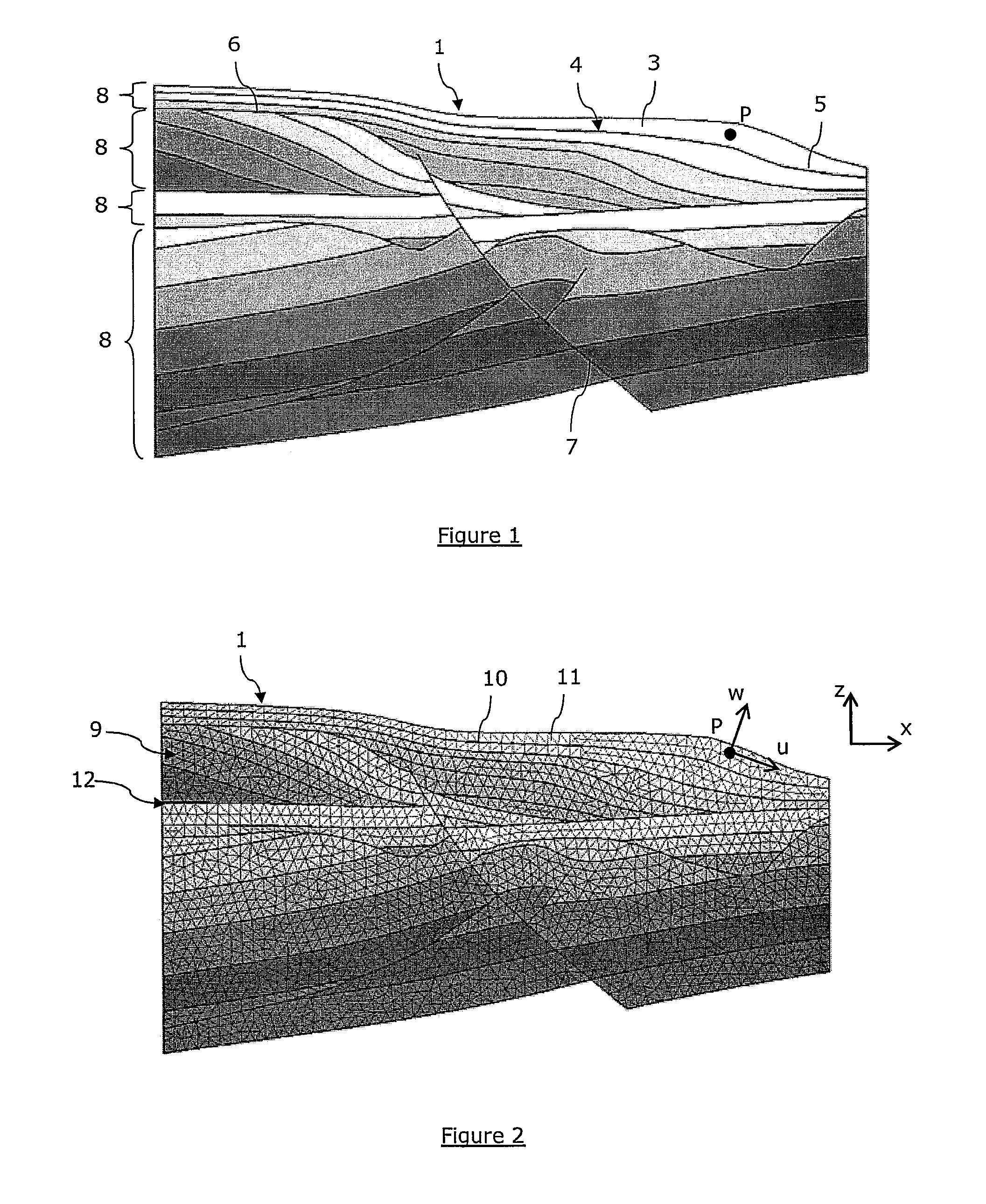
[0128]With reference to FIG. 5, in a first embodiment, the geological domain can be represented by a 3D conformal mesh 9 whose elements 11 are all tetrahedra. The generation of the mesh is not within the scope of the invention and can be done following any classical method known in the art. Each tetrahedron has four facets 12, and each of these four facets can be simply identified with an index between 1 and 4. Facets in the tetrahedral mesh may thus be represented unambiguously by a pair (T, J) where T is a tetrahedron and J an index between 1 and 4. Let us also consider that the data structure representing a single tetrahedron t is encoded so that memory slots are reserved to store and retrieve an array of four integer values A(t)={a1, a2, a3, a4}, each aj being associated with the facet (t, j), the jth facet of t. The values of the aj may be set as follows:[0129]if the facet (t, j) does not match a boundary of set B, then aj=−1,[0130]if the facet (t, j) matches the boundary with ...

second embodiment

[0171]In a second embodiment, the geological domain 1 can be represented by a set M of 2D independent meshes (for example made of triangles 12), each of these meshes representing a boundary 4 of the set B. The generation of the 2D meshes is not within the scope of the invention and can be done following any classical method known in the art. M can be represented for instance by a linear list M={M1, M2, M3, . . . , Mn}. The data structure representing such a triangular mesh Mj is encoded so that memory slots are reserved to store and retrieve an integer value A(Mj). The value of A(Mj) is set so that if the mesh Mj represents the boundary Bi, then A(Mj) is equal to the corresponding geological ID bi (equal to i for example). The value of the A(Mj) may be set during an initialization step taking place at the beginning of the boundary matching step. Then, retrieving all the triangles that correspond to a given boundary Bi of the geological domain may involve the following steps:[0172]fi...


PUM


Abstract

A method for building a depositional space corresponding to a geological domain includes the steps of (i) partitioning the present day geological domain with at least one conformal mesh sensibly matching the boundaries of said geological domain, (ii) calculating depositional coordinates defining a depositional space, wherein the depositional coordinates calculations includes calculations of fields of displacement including simulations of mechanical deformations in the geological domain, using a solid material deformation model. A computer program implementing the method is also described.

Description

FIELD OF THE INVENTION[0001]The general field of the invention is, not limited to, the modeling of stratified terrains in the subsurface, in oil reservoir geosciences notably. The invention pertains to a method for building a virtual and physically-reliable depositional space matching the chronostratigraphic environment at the time of deposition of geological terrains, said depositional space being then used as a computational space where many applications can be run advantageously.[0002]Such applications include accurate modeling and interpolation of geological terrains properties such as porosity or permeability, controlling the quality of seismic reflection data interpretation, or building grids fitting the complex geometry of geological structures.BACKGROUND OF THE INVENTION[0003]There are potentially many applications that benefit from the use of a computational space that models the chronostratigraphic environment at the time of deposition of the terrains (which is referred to...

Claims


Application Information

Patent Timeline
Patent Type & Authority Patents(United States)
IPC IPC(8): G06G7/48
CPCG01V11/00
Inventor LEPAGE, FRANCOIS
Owner SCHLUMBERGER TECH CORP
Why Eureka
Try Eureka