Burner having swirler with corrugated downstream wall sections

a downstream wall and burner technology, applied in the field of burners, can solve the problems of environmental damage, take considerable effort to keep the pollutants as low as possible, and achieve the effect of reducing the fraction of nitrous oxid

Inactive Publication Date: 2012-11-27
SIEMENS AG
View PDF11 Cites 27 Cited by
  • Summary
  • Abstract
  • Description
  • Claims
  • Application Information

AI Technical Summary

Benefits of technology

[0008]With respect to the mentioned state of the art it is an objective of the invention to provide a burner, in particular a gas turbine burner, enabling fine tuning of fuel / air mixing so as to provide a homogenous fuel / air mixture.
[0011]By such a design of the downstream section of the air passage wall a controlled fuel placement at the exit of the air passage is obtained. Thereby, a fine tuning of fuel / air mixing for improved NOx emissions is enabled. Especially, a better distribution of the injected fuel can be achieved in the swirler air passage. In addition, the homogeneity of the fuel / air mixture at the downstream end of the swirler air passage can be increased.
[0013]It is particularly advantageous when at least one first fuel injection opening is arranged at an upstream section of the swirler vane which adjoins the air inlet opening. This allows for a long mixing path in the air passage. The opening can be a nozzle.
[0018]The inventive burner can be used in a turbine engine, in particular in a gas turbine engine, or in a furnace. The inventive burner helps to reduce the fraction of nitrous oxide in the exhaust gases of the turbine engine or the furnace, respectively.

Problems solved by technology

However, burning the fuel leads to a number of undesired pollutants in the exhaust gas which can cause damage to the environment.
Therefore, it takes considerable effort to keep the pollutants as low as possible.

Method used


Image

  • Burner having swirler with corrugated downstream wall sections
  • Burner having swirler with corrugated downstream wall sections
  • Burner having swirler with corrugated downstream wall sections

Examples


Embodiment Construction

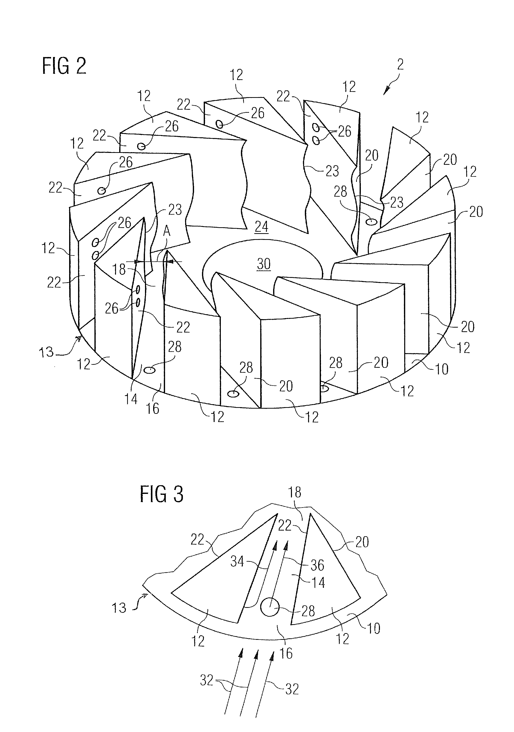
[0028]FIG. 1 shows a longitudinal section through a combustor. The combustor comprises in flow direction series a burner with swirler portion 2 and a burner-head portion 1 attached to the swirler portion 2, a transition piece being referred as combustion pre-chamber 3 and a main combustion chamber 4. The main combustion chamber 4 has a diameter being larger than the diameter of the pre-chamber 3. The main combustion chamber 4 is connected to the pre-chamber 3 via a dome portion 10 comprising a dome plate 11. In general, the transition piece 3 may be implemented as a one part continuation of the burner 1 towards the combustion chamber 4, as a one part continuation of the combustion chamber 4 towards the burner 1, or as a separate part between the burner 1 and the combustion chamber 4. The burner and the combustion chamber assembly show rotational symmetry about a longitudinally symmetry axis S.

[0029]A fuel conduit 5 is provided for leading a gaseous or liquid fuel to the burner which...


PUM


Abstract

The invention relates to a burner, in particular a gas turbine burner, comprises: at least one swirler, the swirler having at least one air inlet opening, at least one air outlet opening positioned downstream to the air inlet opening and at least one swirler air passage extending from the at least one air inlet opening to the at least one air outlet opening which is delimited by swirler air passage walls, the air passage walls comprising downstream wall sections adjoining the at least one air outlet opening; and a fuel injection system which comprises fuel injection openings arranged in at least one swirler air passage wall so as to inject fuel into the swirler air passage; in which at least the downstream section of one air passage wall is corrugated.

Description

CROSS REFERENCE TO RELATED APPLICATIONS[0001]This application is the US National Stage of International Application No. PCT / EP2007 / 051825, filed Feb. 27, 2007 and claims the benefit thereof. The International Application claims the benefits of European application No. 06012058.1, filed Jun. 12, 2006, both of the applications are incorporated by reference herein in their entirety.FIELD OF THE INVENTION[0002]The present invention relates to a burner, in particular to a gas turbine burner, having an air inlet duct and at least one swirler disposed in said air inlet duct.BACKGROUND OF THE INVENTION[0003]In a gas turbine burner a fuel is burned to produce hot pressurised exhaust gases which are then led to a turbine stage where they, while expanding and cooling, transfer momentum to turbine blades thereby imposing a rotational movement on a turbine rotor. Mechanical power of the turbine rotor can then be used to drive a generator for producing electrical power or to drive a machine. Howe...

Claims


Application Information

Patent Timeline
Patent Type & Authority Patents(United States)
IPC IPC(8): F02C1/00F02G3/00B05B7/10
CPCF23C7/004F23R3/14F23R3/286F23C2900/07001
Inventor WILBRAHAM, NIGEL
Owner SIEMENS AG
Why Eureka
Try Eureka