
Screwdriving system with variably adjustable screwdriving spindles

a screwdriver and spindle technology, which is applied in the direction of wheel mounting apparatus, manufacturing tools, transportation and packaging, etc., can solve the problem of requiring a relatively large amount of effort to use the aforementioned screwdriver, and achieve the effect of preventing the rotation of the screwdriver and enabling optimal utilization of work spa

Inactive Publication Date: 2012-11-27
ROBERT BOSCH GMBH
View PDF28 Cites 3 Cited by
  • Summary
  • Abstract
  • Description
  • Claims
  • Application Information

AI Technical Summary

Benefits of technology

[0006]This method has the advantage that the screwdriving system can be mounted on a stationary or variable device, and the screwing operation can be performed in automated fashion. Because of the corresponding location of fastening means and screwdriving devices, many geometrically located, identical or different fastening means, as is usual for instance in fastening wheel rims to motor vehicles, can be screwed into a workpiece simultaneously and thus in a time-saving way. It is also advantageous that different screws or nuts can be screwed in, since the drive outputs can also have different tool bits, such as bits for different wrench widths, or different recess. The number of drives required is reduced; less work space is needed, and there are savings in weight and expense.
[0022]If the screwdriving system is used for installing wheel rims or other vehicle components of the same or different dimensions, then with the same screwdriving system, wheel rims of different pitch circle diameters and with different tool bits or tool bit shapes can be screwed on. This saves both production costs and material costs, especially if the device of the invention is used for equipping motor vehicles with wheel rims, and the device is in particular included in a motor vehicle production line.LIST OF REFERENCE NUMERALS

Problems solved by technology

If many identical fastening means, located in accordance with a fixed geometric shape, such as screws / nuts for securing a wheel rim, are to be screwed in as fast as possible, then using the aforementioned screwdriving device entails relatively major effort, since the screwdriving device has to be manually realigned and positioned for each screw / nut combination.

Method used


Image

  • Screwdriving system with variably adjustable screwdriving spindles
  • Screwdriving system with variably adjustable screwdriving spindles
  • Screwdriving system with variably adjustable screwdriving spindles

Examples


Embodiment Construction

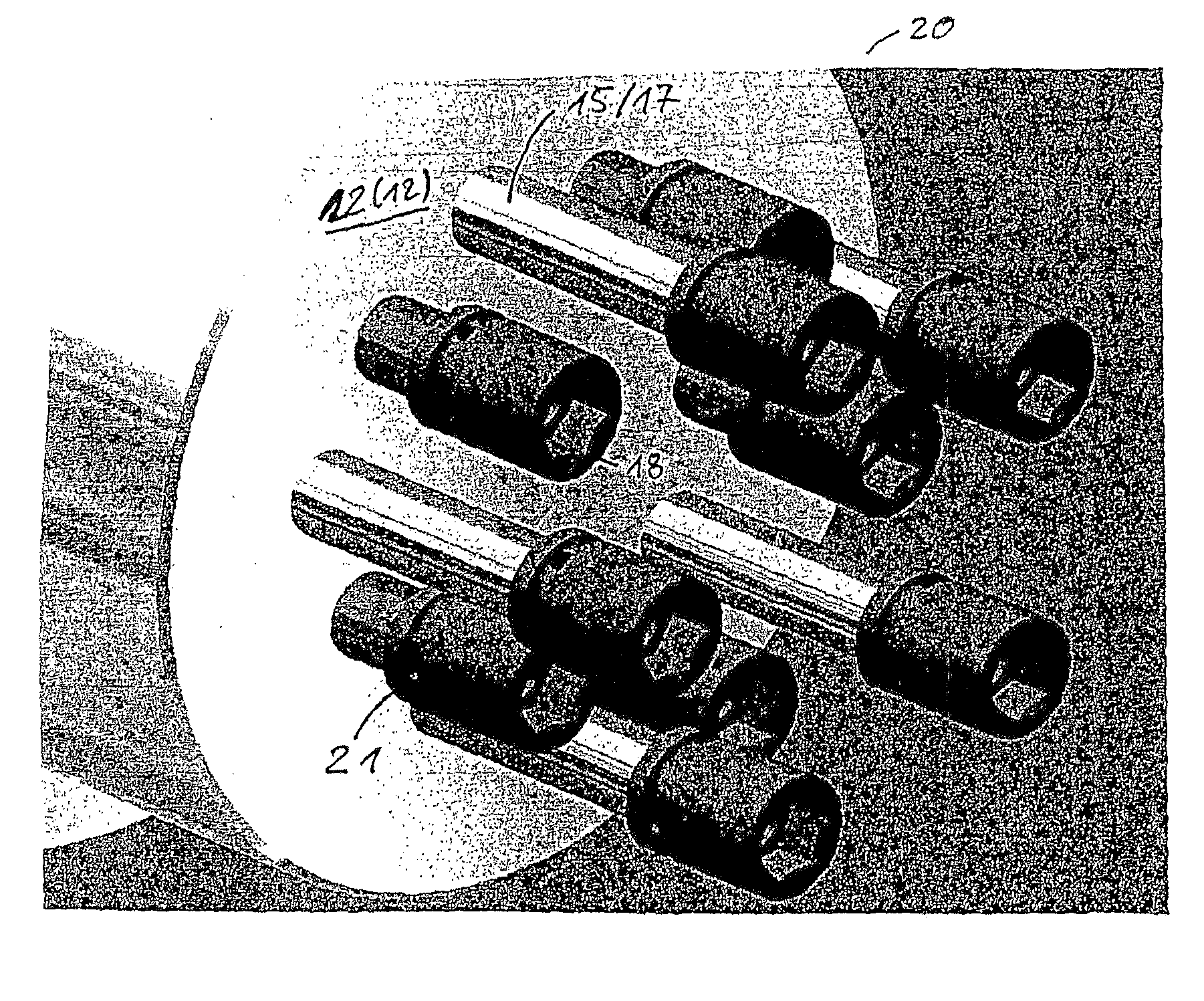
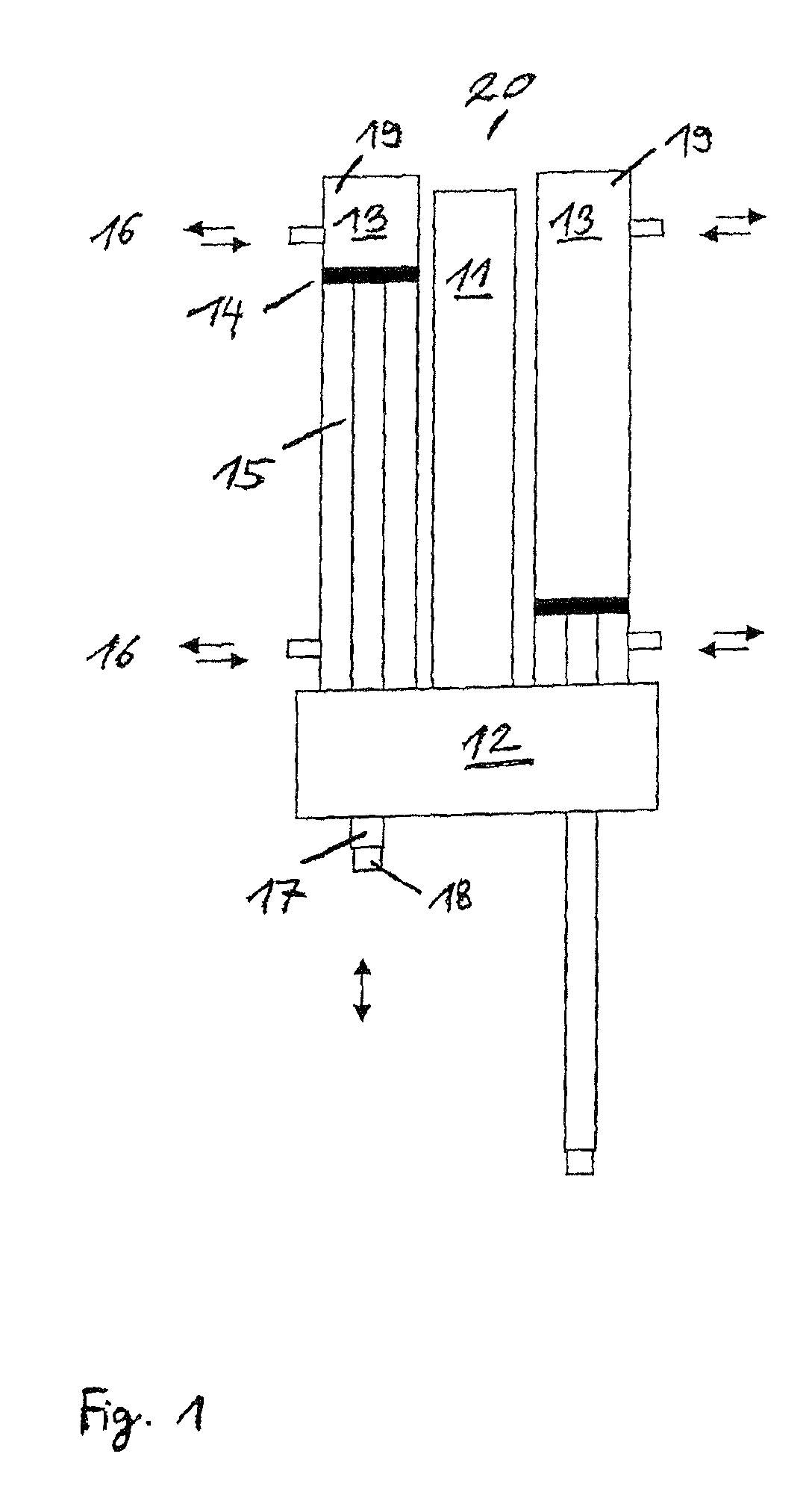
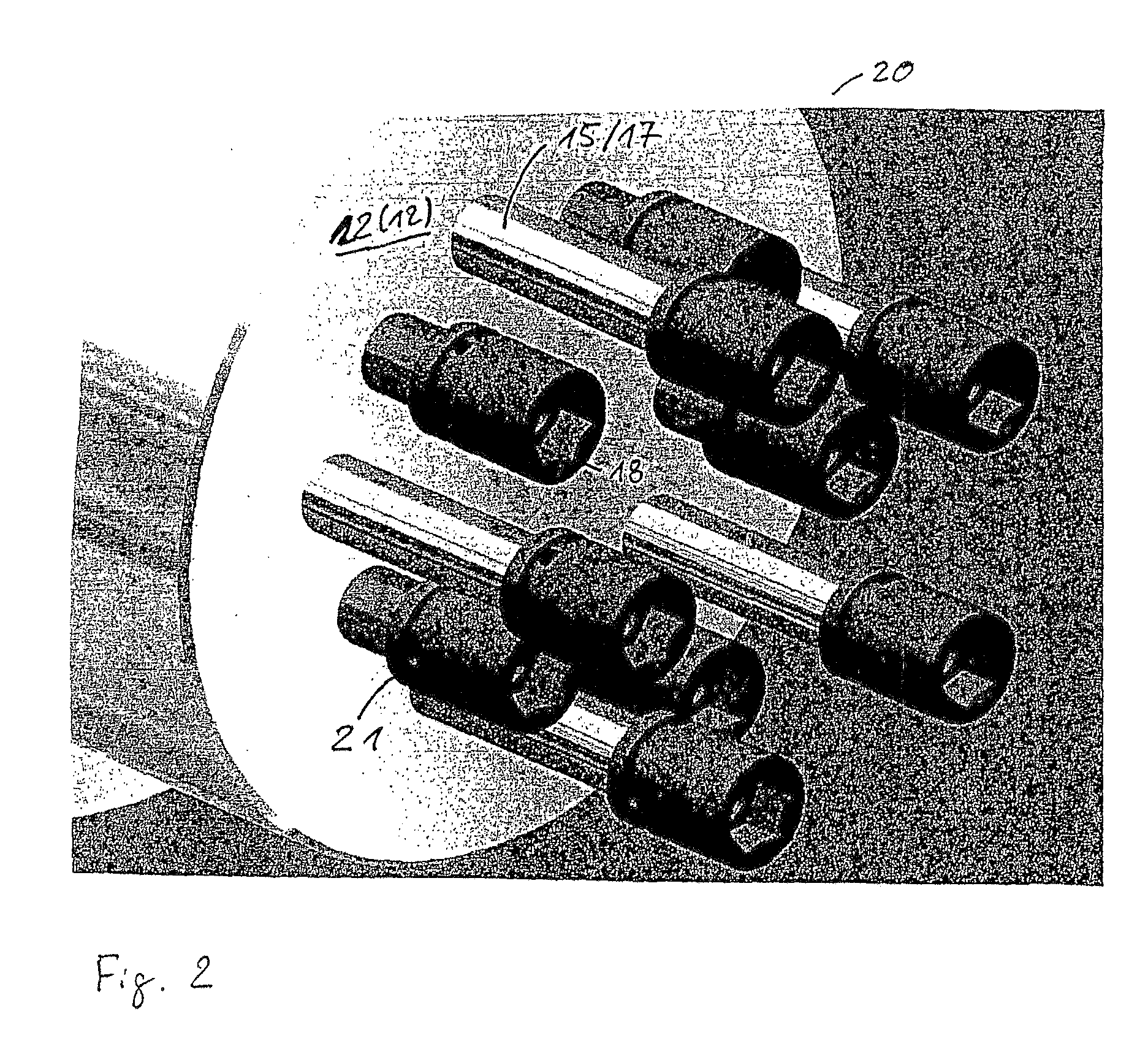
[0026]The double feed drive output 20 shown in FIG. 1 includes a spindle drive 11, a gear 12, and two feed drive outputs 19, each with one cylinder 13, one piston 14, one spline shaft 15, two compressed-air connections 16, and one drive output 17 with a tool bit receptacle 18.

[0027]By means of the gear 12, a spindle drive 11 drives the spline shafts 15 of each of the two feed drive outputs 19, which are additionally axially displaceable by means of the piston 14 inside the cylinder 13 in the direction of the axis of rotation of a spline shaft 15. The feed is implemented by means of compressed air, because the emergence of the spline shaft 15 from the cylinder is implemented by means of a first compressed-air connection 16 (FIG. 1, top), and the retraction of the spline shaft into the cylinder is implemented by means of a second compressed-air connection 16 (FIG. 1, bottom). A hydraulically or electrically operated cylinder (for instance with a revolving ball spindle) would also be c...


PUM

PropertyMeasurementUnit
Torqueaaaaaaaaaa

Abstract

A method for attaching a plurality of fasteners located along a circular path uses a screwdriving device that has feed drive outputs. The drive outputs correspond to the fasteners, are located on a circular path and include a screwdriving tool bit. During the method, the drive outputs are extended from a position of repose to a working position and the screwdriving tool bit, located at the fastener, screws in the fastener. The feed drive outputs are located on circular paths of different diameters and only those drive outputs located on a particular circular path, which corresponds with a circular path on which the fasteners are located, leave their position of repose. The number of feed drive outputs corresponds to the number of fasteners.

Description

BACKGROUND OF THE INVENTION[0001]The invention relates to a method for screwing in a plurality of fastening means, such as screws and nuts, and to a device for performing the method.[0002]In Published European Patent Application EP 0203 370 A1, a screwdriving device with a motor-driven screwdriver is shown. If many identical fastening means, located in accordance with a fixed geometric shape, such as screws / nuts for securing a wheel rim, are to be screwed in as fast as possible, then using the aforementioned screwdriving device entails relatively major effort, since the screwdriving device has to be manually realigned and positioned for each screw / nut combination.SUMMARY OF THE INVENTION[0003]The object of the invention is to screw a group of a plurality of fastening means into a workpiece simultaneously and with the least possible effort.[0004]The object is attained by means of a method for attaching a plurality of fastening means, in particular located along a circular path, using...

Claims


Application Information

Patent Timeline
IPC IPC(8): B25B21/00B25B17/00
CPCB23P19/069B60B29/006Y10T29/49963
Inventor VOLLMUTH, MICHAELOEHME, KLAUS
Owner ROBERT BOSCH GMBH
Learn More