
Charging system for a communication system

a communication system and charging system technology, applied in the field of charging in a communication system, can solve the problems of inflexible and complex to implement and operate a more complex system and communication service, high undesirable to have to frequently modify the operation or functionality of the charging centre, charging information, etc., to facilitate charging, improve or facilitate charging, and improve flexibility

Inactive Publication Date: 2012-11-27
GOOGLE TECHNOLOGY HOLDINGS LLC
View PDF29 Cites 12 Cited by
  • Summary
  • Abstract
  • Description
  • Claims
  • Application Information

AI Technical Summary

Benefits of technology

The invention aims to improve charging in cellular communication systems by using a publish / subscribe system for distributing charging information flexibly and dynamically between different entities and parties. This allows for better flexibility and dynamic variations in charging, such as temporary discount offers paid for by a third party. The system also allows for independent registration and authentication of charging proxies for different charging topics. The communication system may be a cellular communication system, with both centralized and distributed implementations. Overall, the invention provides a more efficient and flexible charging solution for cellular communication networks.

Problems solved by technology

However, although such an approach is suitable for simpler cellular communication systems providing a relatively small set of communication services, it also tends to have a number of associated disadvantages.
Specifically, it tends to be inflexible and complex to implement and operate for more complex systems and communication services.
However, as correct operation of the charging centre is crucial for maximizing customer satisfaction, it is highly undesirable to have to frequently modify the charging centre operation or functionality.
Furthermore, the centralized approach results in the charging information being concentrated either physically at the charging centre or logically under control of one administrative domain and not easily being available or distributable to other interested parties.
Thus, sharing or distribution of charging data is not easily achieved.
As a specific example, the conventional charging approach is not optimally suited to dynamic and flexible composite services that involve a plurality of different communication services and dynamic service offerings from a number of different parties.

Method used


Image

  • Charging system for a communication system
  • Charging system for a communication system
  • Charging system for a communication system

Examples


Embodiment Construction

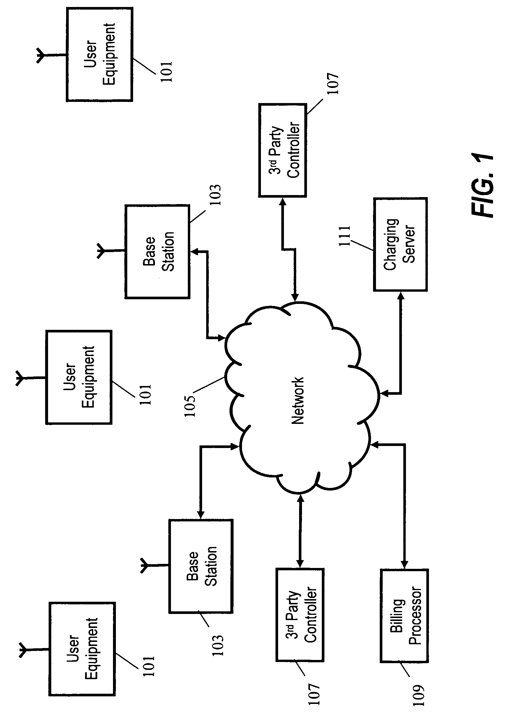
[0019]FIG. 1 illustrates an example of a cellular communication system in accordance with some embodiments of the invention. It will be appreciated that although the following description focuses on embodiments of the invention applicable to a cellular communication system, the invention is not limited to this application but may be applied to many other communication systems.

[0020]The cellular communication system may be a GSM / UMTS cellular communication system which supports a plurality of user equipments via radio air interface communications. In other embodiments, the cellular communication system may for example be a cellular communication systems comprising different types of Radio Access Networks (RANs) coupled together via a core network. As another example, the cellular communication system may be a heterogeneous communication system comprising a plurality of (semi-) independent communication systems including for example Wireless Local Area Network (WLAN) RANs (including a...


PUM


Abstract

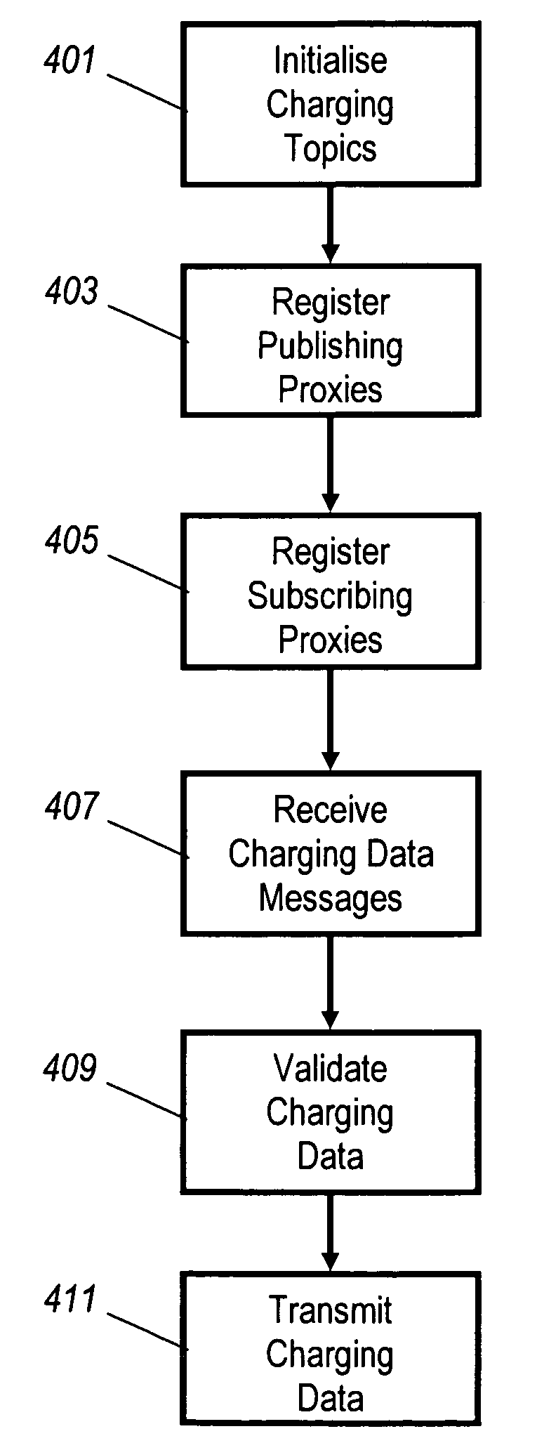
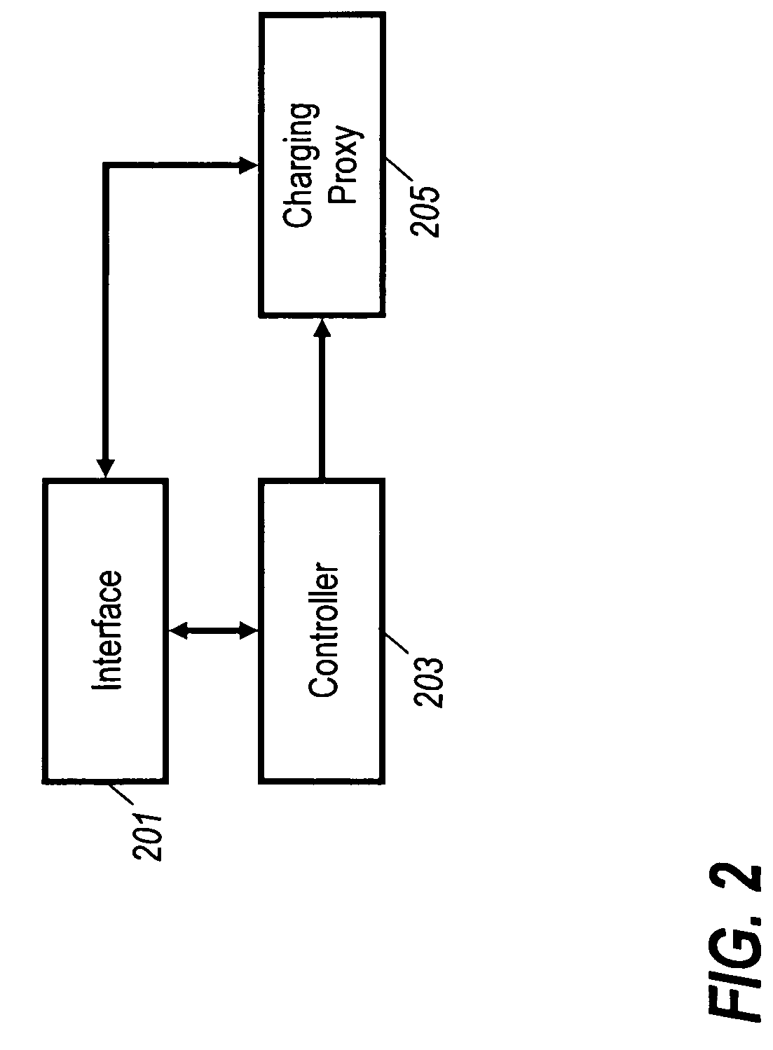
A communication system comprises network elements (103, 105, 107, 109) and user equipments (101), at least some of which comprise a charging proxy (205). The system further comprises a charging server (111) which includes a topic controller (305) for initializing charging topics where each charging topic is associable with charging data. The charging server (111) furthermore comprises functionality for registering proxies as subscribing proxies or publishing proxies (or both) for the different charging topics. A receiver (301, 311) receives charging data messages from charging proxies and validates a first set of charging data belonging to a first charging topic in response to a first set of charging proxies registered as publishing proxies for the first charging topic. A charging data transmitter (313) transmits the first set of charging data to a second set of charging proxies registered as subscribing proxies for the first charging topic.

Description

FIELD OF THE INVENTION[0001]The invention relates to charging in a communication system and in particular, but not exclusively, to charging for composite communication services.BACKGROUND OF THE INVENTION[0002]Cellular communication systems for providing, e.g., mobile communication have become ubiquitous over the last decades. For example, 2nd Generation systems, such as the Global System for Mobile communication (GSM), and 3rd Generation systems, such as the Universal Mobile Telecommunication System (UMTS), have been deployed or are being deployed in most countries. Furthermore, there is a continuous trend towards further improving and enhancing cellular communication systems which have led to the development and standardization of a number of additions or enhancements to the systems.[0003]There is an increasing trend towards providing increasingly flexible and diverse communication services in cellular communication systems. For example, initially 2nd Generation communication syst...

Claims


Application Information

Patent Timeline
Patent Type & Authority Patents(United States)
IPC IPC(8): H04M11/00
CPCH04L12/1496H04M2215/204H04L12/1403H04M2215/0112H04L12/14G06Q30/02H04L12/1475H04L29/08081H04M15/81H04M2215/0184H04M15/80H04L67/00H04M2215/74H04M15/8083H04M15/00H04W4/24H04M2215/0196H04M15/42H04M15/68G06Q20/14H04M15/43
Inventor VAKIL, FARAMAKBOSCOVIC, DRAGAN M.FRATTI, MARCOKUMAR, SURENDER
Owner GOOGLE TECHNOLOGY HOLDINGS LLC
Learn More