
Method of controlling the closing phase of a clutch of an automated automobile transmission system

a technology of automatic automobile transmission and closing phase, which is applied in the direction of adaptive control, fluid couplings, instruments, etc., can solve the problems of not being able to explicitly manage these constraints, unable to easily translate specifications, and long calibration time to fill in maps

Inactive Publication Date: 2012-11-27
INST FR DU PETROLE
View PDF27 Cites 4 Cited by
  • Summary
  • Abstract
  • Description
  • Claims
  • Application Information

AI Technical Summary

Benefits of technology

The invention is a method for controlling the clutch in an automated transmission system of a vehicle. The method uses a control law called CMPC to control the sliding velocity and engine speed of the vehicle. The method translates the driver's request in terms of sliding velocity and engine speed, and uses constraints on the actuators of the engine and clutch to ensure safety and comfort during clutch engagement. The method selects a control trajectory that respects the constraints and controls the clutch with the selected trajectory. The invention allows for real-time control of the automobile clutch in an automated transmission system and improves the driving quality.

Problems solved by technology

This mapping control, typical of standard vehicles, does not allow readily translating the specifications to be met during clutch closing which are compliance with the driver's requests, comfort and maintenance of powertrain smooth running.
Besides, a long calibration time to fill in the maps.
Now, these techniques cannot explicitly manage these constraints to ensure that one or more variables of the system to be controlled (inputs, outputs or state), or their derivatives, do not exceed certain limits set as specifications.

Method used


Image

  • Method of controlling the closing phase of a clutch of an automated automobile transmission system
  • Method of controlling the closing phase of a clutch of an automated automobile transmission system
  • Method of controlling the closing phase of a clutch of an automated automobile transmission system

Examples


Embodiment Construction

[0036]Progressive closing of a clutch and its coordination with the production of a given engine torque is a key phase of automated transmission control. The following points have to be ensured during this phase:

maintenance of the powertrain (the system) smooth running: no stalling, no engine over-revving;

driver's comfort: oscillation minimization upon clutch closing;

respect for the driver's request: for example, shorter standing start if one presses the accelerator pedal down harder, standing start abandoned if one releases the pedal.

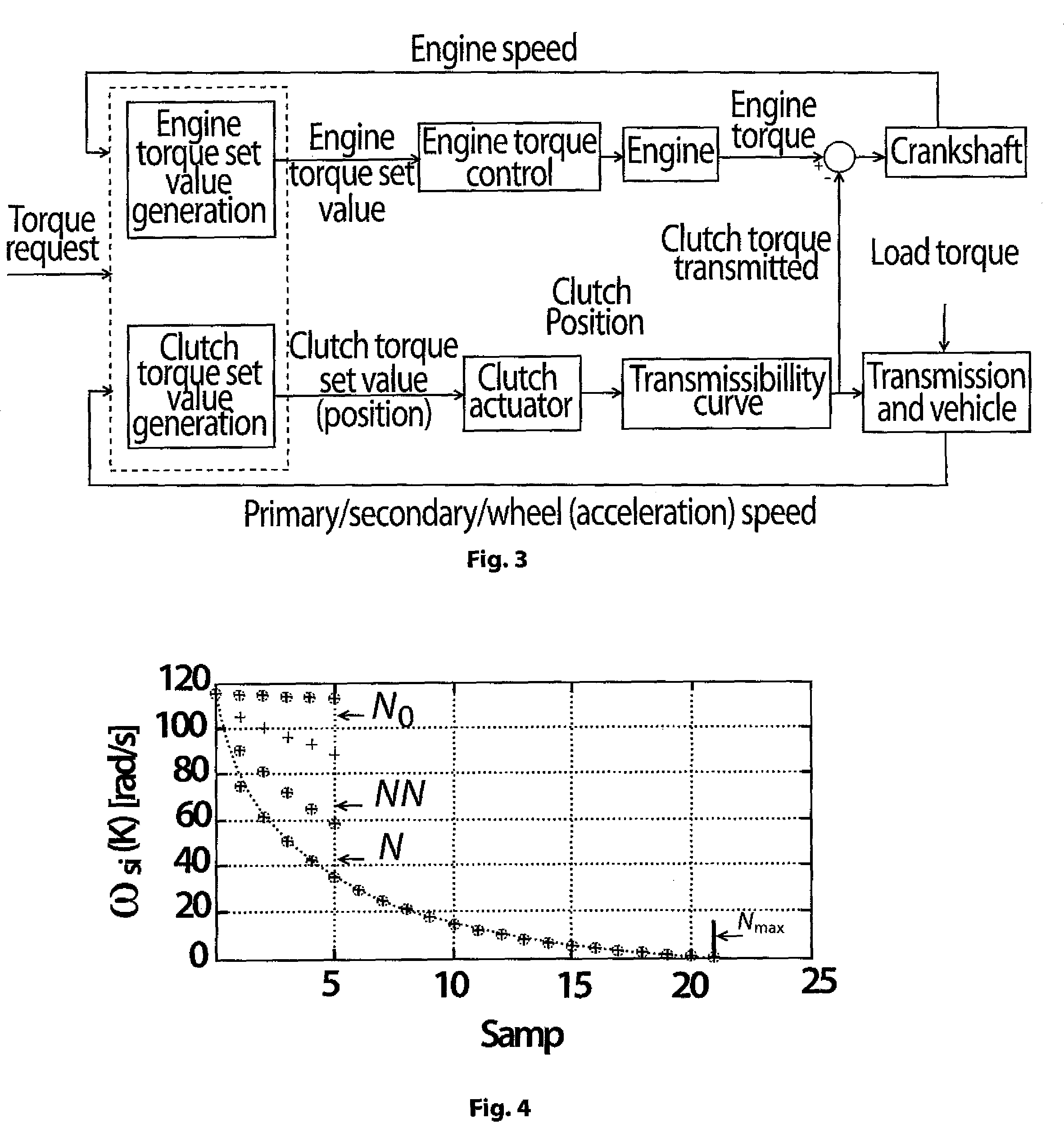
[0037]According to the invention, in order to take into account these specifications in a transparent manner (for the driver), an approach based on a control law that can optimize a criterion while managing constraints is used. The technique referred to as constrained model predictive control (CMPC) described, among others, in D. Q. Mayne, J. B. Rawlings, C. V. Rao, and P. O. Scokaert, “Constrained Model Predictive Control: Stability and Optimality,” A...


PUM


Abstract

A method of controlling an automobile clutch in an automated transmission system with a CMPC control is disclosed having application to vehicle clutch control in an AMT system. The driver's request is translated in terms of sliding velocity ωsl. Constraints on the engine and clutch actuators are defined to respect their operating limits, and driving quality constraints are defined to guarantee comfort during the clutch engagement phase. In order to meet these quality constraints, a reference trajectory is defined for ωsl as a function of the clutch engagement time. An analytical expression allowing real-time calculation of a set of control trajectories with a CMPC control law is then defined from the expression of this reference trajectory. The trajectory respecting the constraints on the actuators is selected from among all these control trajectories. Finally, the clutch is controlled with the selected control trajectory.

Description

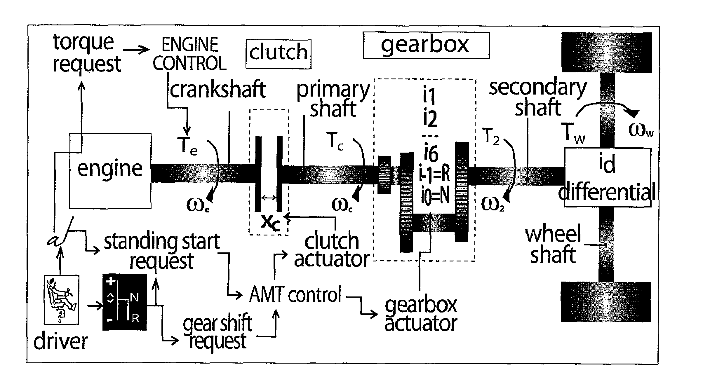
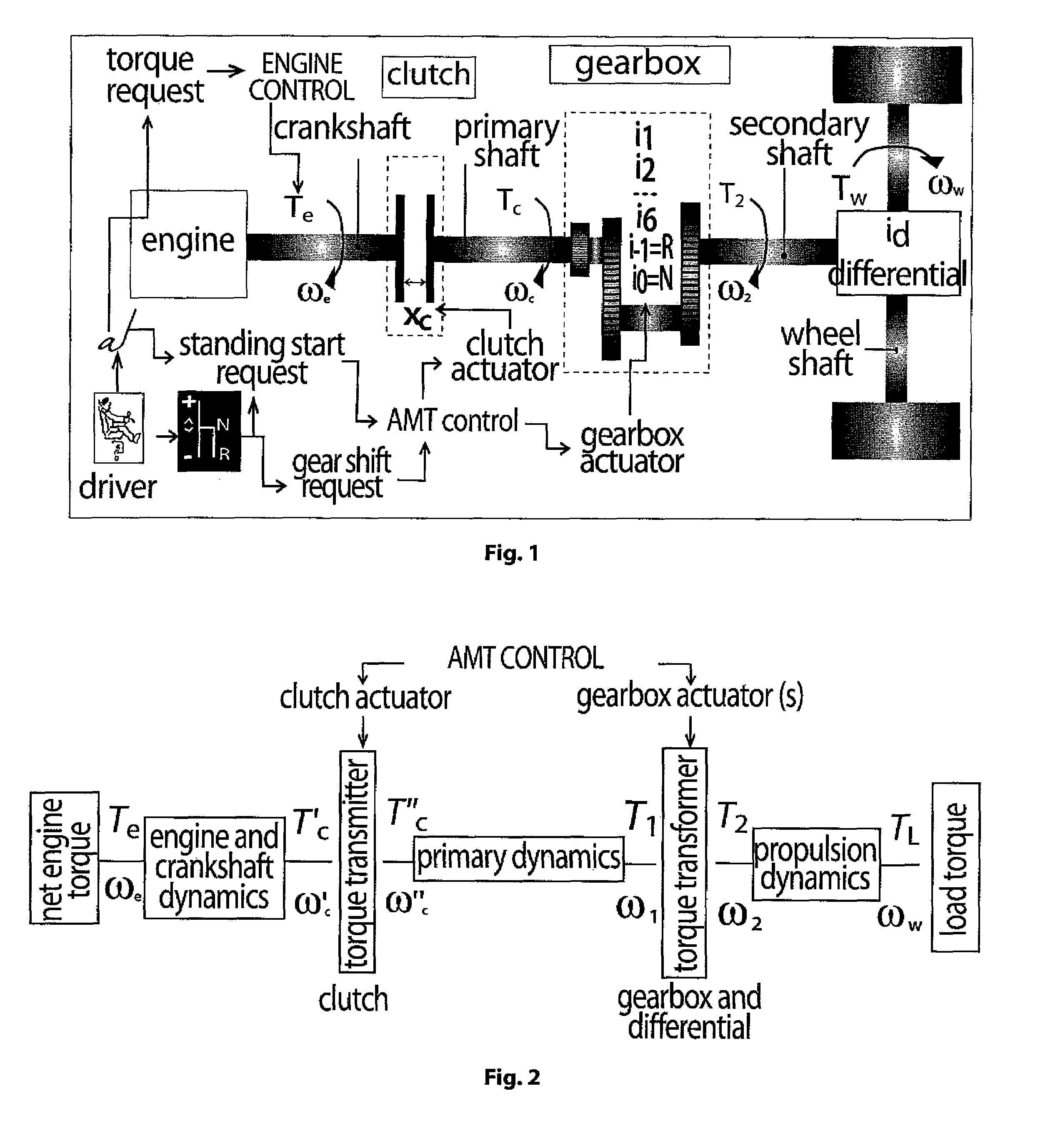
BACKGROUND OF THE INVENTION[0001]1. Field of the Invention[0002]The present invention relates to automatic control systems for vehicle engines. In particular, the invention relates to a method for controlling the closing phase of a clutch in an automated automobile transmission system.[0003]2. Description of the Prior Art[0004]Automated transmission systems, or automated manual transmission (AMT) systems, are an intermediate solution between conventional manual transmissions and automatic transmissions. Unlike the latter, characterized by complex mechanical components such as torque converters and epicyclic trains, automated transmissions use devices (clutch, gearbox) having conventional mechanics controlled not by the driver but by one or more on-board control unit(s). FIG. 1 shows a generic diagram of an automated transmission. FIG. 2 shows a conceptual diagram of an automated transmission.[0005]Any automated transmission control system, having on-board one or more ECUs (Electroni...

Claims


Application Information

Patent Timeline
Patent Type & Authority Patents(United States)
IPC IPC(8): B60W10/02
CPCF16D48/06F16D2500/30406F16D2500/3067F16D2500/30816F16D2500/3144F16D2500/50684Y10T477/6203F16D2500/7044F16D2500/70663F16D2500/708Y10T477/6392Y10T477/60Y10T477/638F16D2500/70426
Inventor TONA, PAOLINOAMARI, RACHIDALAMIR, MAZEN
Owner INST FR DU PETROLE
Learn More