
Serial controller and bi-directional serial controller

a serial controller and controller technology, applied in the direction of generating/distributing signals, digital transmission, instruments, etc., can solve the problems of reducing the error detection efficiency of serial rgb clusters, severely distorted signal waveform of spot lights at the latter level,

Active Publication Date: 2012-11-27
MACROBLOCK INC
View PDF11 Cites 25 Cited by
  • Summary
  • Abstract
  • Description
  • Claims
  • Application Information

AI Technical Summary

Benefits of technology

The present invention is a serial controller that solves the problem of waveform distortion in the driving clocks of spot lights at all stages. It also allows for bi-directional transmission of data signals between spot lights at all stages. The serial controller includes an inverter, serial position detector, synchronous clock generator, serial register, half-cycle delay unit, and data directing unit. The technical effect of the invention is that it ensures synchronous transmission of data between spot lights at all stages and allows for bi-directional transmission of data signals.

Problems solved by technology

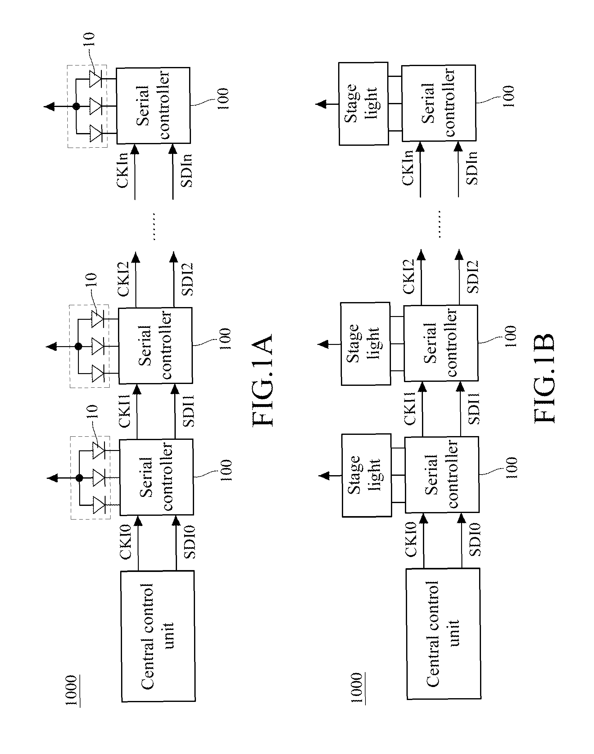
However, the problem of this serial RGB cluster lies in that the driving clock for driving the spot lights at each stage in the series is not a single global signal.
Therefore, regarding the signal of the driving clock at one stage in the series, when the duty cycle of the driving clock offsets due to the capacitance effect or accumulative effect generated in the transmission distance, e.g., the time of the signal of the driving clock at the high level is unequal to the time of the signal at the low level, and in this circumstance, for the serial RGB cluster formed by connecting multilevel spot lights in series, the signal waveform of the driving clock of the spot lights at the latter level is severely distorted due to the multilevel accumulative effect.
This method not only reduces the error detection efficiency of the serial RGB cluster, but also as abovementioned causes the waveform distortion of the driving clock.

Method used


Image

  • Serial controller and bi-directional serial controller
  • Serial controller and bi-directional serial controller
  • Serial controller and bi-directional serial controller

Examples


first embodiment

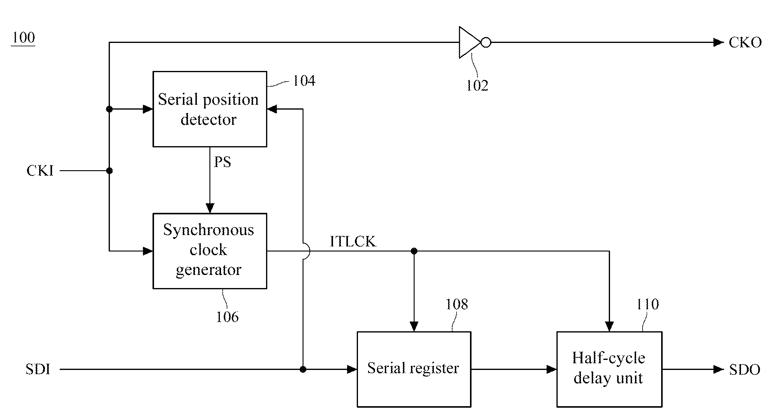
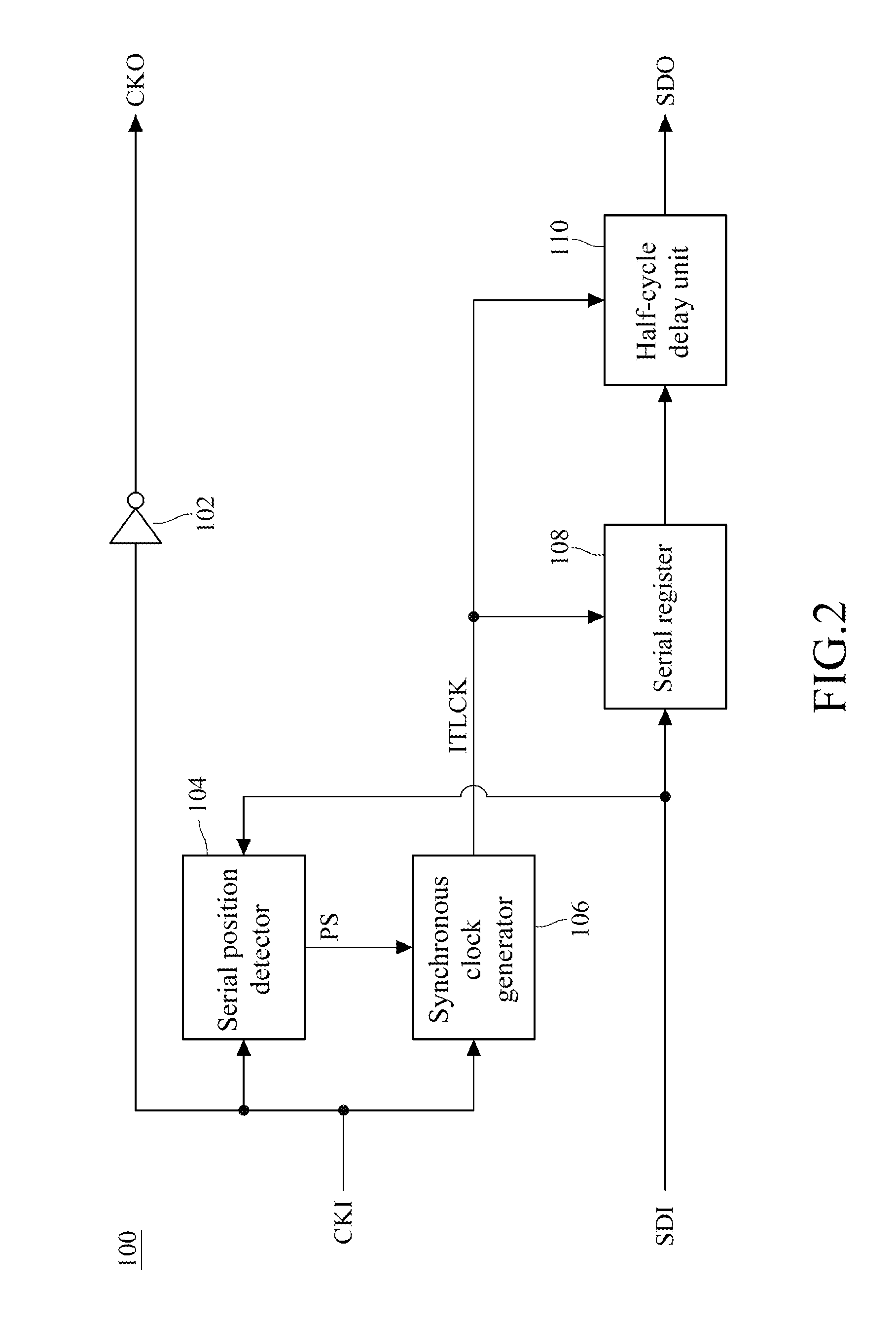
[0047]FIG. 2 is a schematic block view illustrating functions of the serial controller according to the present invention. The serial controller 100 is adapted to receive an external clock CKI and an input data SDI and output an inverted clock CKO and an output data SDO. Taking the serial controller 100 at the 0th stage of the serial cluster 1000 as shown in FIG. 1A as an example, the external clock CKI and the inverted clock CKO in FIG. 2 are respectively corresponding to the clock signals CKI0 and CKI1 in FIG. 1A. The input data SDI and the output data SDO in FIG. 2 are respectively corresponding to the data signals SDI0 and SDI1 in FIG. 1A. Hereinafter, the serial controller 100 at the 0th stage of the serial cluster 1000 is taken as an example for illustration, but the present invention is not limited thereto. That is to say, the serial controller 100 at any stage of the serial cluster 1000 falls within the protection scope of the present invention, and only the serial controlle...

second embodiment

[0059]Next, in the serial cluster 1000, since serial transmission is implemented among the serial controllers 100 connected at all stages, and the data signals (the input data SDI and the output data SDO) are delivered one stage to another, the serial controller 100 at each stage needs to identify whether the current data signal is fed to the serial controller 100 at this stage through a decoding mechanism therein. When the serial cluster 1000 is interfered by noises in long-distance transmission or encounters circumstances like hot-plug, errors may occur to the decoding mechanism of the serial controller 100 and cause chaos. To solve this problem, according to the present invention, as shown in FIG. 7A, the serial controller 100a may further comprise a timeout detector 700 for receiving the external clock CKI, and outputting a reset signal RESET to the serial register 108 when the external clock CKI satisfies such a certain condition that the serial controller 100a can be triggered...

third embodiment

[0063]FIG. 7B is a schematic block view illustrating functions of a serial controller 100b according to the present invention. The timeout detector 700 and the serial position detector 104 are integrated as a single circuit block to reduce the extra fabricating cost of the circuit and reduce the using area of some chips. Herein, the serial position detector 104 may determine the position of the serial controller 100 in the serial cluster 1000 through detection of the reset signal RESET and the external clock CKI.

[0064]For example, referring to FIG. 9A, when the timeout detector 700 generates the reset signal RESET and the serial position detector 104 detects that the external clock CKI is at the high level, the serial position detector 104 outputs the odd signal as the position signal PS. Otherwise, as shown in FIG. 9B, when the timeout detector 700 generates the reset signal RESET and the serial position detector 104 detects that the external clock CKI is at the low level, the seri...


PUM


Abstract

A serial controller is adapted to receive an external clock and an input data, and output an inverted clock and an output data. The serial controller includes an inverter, a serial position detector, a synchronous clock generator, a serial register, and a half-cycle delay unit. Thereby, through the serial controller, the problem that the data signal and the driving clock are not synchronous when the clock series are inverted is avoided. Besides, a bi-directional serial controller further includes an identification unit and a data directing unit, and the serial controller is enabled to return the current status to a central control unit to serve as the reference for error detection.

Description

CROSS-REFERENCE TO RELATED APPLICATIONS[0001]This non-provisional application claims priority under 35 U.S.C. §119(a) on Patent Application No(s). 099123578 filed in Taiwan, R.O.C. on Jul. 16, 2010, the entire contents of which are hereby incorporated by reference.BACKGROUND OF THE INVENTION[0002]1. Field of Invention[0003]The present invention relates to a serial controller and a bi-directional serial controller, and more particularly to a serial controller and a bi-directional serial controller for synchronously transmitting data signals at all stages in a series with an inverted clock.[0004]2. Related Art[0005]In recent years, with the raising of the worldwide issue of energy-saving and reducing CO2 emission, in the design of architectural outdoor illumination, decorative illumination, or scenario illumination for commercial purposes, light-emitting diodes (LEDs) are more widely used as illumination apparatus. For example, since the RGB cluster formed by red, blue, and green LEDs...

Claims


Application Information

Patent Timeline
Patent Type & Authority Patents(United States)
IPC IPC(8): G06F13/42H04L7/00H05B44/00
CPCH05B33/0842H05B37/0254H05B47/18H05B45/30H05B45/325H05B47/184H05B45/00H05B45/46
Inventor WU, KEN TANGLEE, CHENG JUNG
Owner MACROBLOCK INC
Learn More