Method and associated apparatus for assembling and testing a plumbing system

a technology for plumbing systems and components, applied in the field of plumbing systems, can solve the problems of difficult and time-consuming interconnection of common bathroom fixtures such as bathtubs, easy misplacement of plugs and/or caps, and difficulty in identifying them, so as to facilitate the integration of various drain pipes and facilitate the field testing for leaks. , the effect of simplifying the installation of the bathtub

Inactive Publication Date: 2012-12-04
WCM IND INC
View PDF235 Cites 25 Cited by
  • Summary
  • Abstract
  • Description
  • Claims
  • Application Information

AI Technical Summary

Benefits of technology

[0009]It is one aspect of the present invention to facilitate this interconnection by providing an elbow with a flange protruding therefrom. More specifically, embodiments of the present invention employ a flange that is spaced from an end of the elbow that will be associated with the bathtub. The end, thus, defines a shoulder that is adapted to receive a cylindrical adapter having an obstructed end that prevents the flow of fluid through the cylindrical fitting and elbow. In one embodiment, the cylindrical fitting includes exterior threads that receive a nut.
[0012]It is another aspect of the invention to provide a method of installing a drain assembly that can be accomplished by a single individual. A related aspect of the invention is to provide a method of installing a bathtub drain assembly that allows for ease in field testing for leaks. Yet another aspect of embodiments of the present invention is to provide a method of installing the drain assembly that eliminates the need for the removal of a strainer body often associated with drain assemblies. In accordance with these and other aspects, one method includes inserting an L-shaped drain pipe having a threaded upper end and an annular flange covered by a membrane, through a drain port of the bathtub, such that the annular flange rests on a bottom surface of the bathtub. Next, a lock washer is threadingly engaged to the inner end of the drain pipe to the threaded portion. The other end of the L-shaped drain pipe is then connected to the drain system of the building. The assembly can then be tested for leaks. Once it is determined that no leaks are present, the membrane is removed from the flange on the upper end of the drain pipe. Finally, a finished cover is installed on the annular flange.
[0013]It is yet another aspect of the present invention to provide a bathtub drain pipe assembly that facilitates integration of the various drain pipes mentioned thus far to the bathtub. Embodiments of the present invention thus include a flexible hollow tube instead of rigid drain pipes that simplifies the installation of the bathtub to the plumbing system. The flexible tube of embodiments of the present invention has the added benefit of being easily modifiable and possesses a smooth inner surface to prevent the often unsanitary trapping of fluid with the flexible hollow tube.
[0015]It is an aspect of the embodiment of the present invention to combine some or all of the above-described aspects to provide a system that facilitates interconnection of the bathtub to the plumbing system of a structure. More specifically, it is contemplated to use aspects described above, provided below, or apparent to one skilled in the art in conjunction to alleviate all of the difficulties noted above that are associated with interconnecting a bathtub to a plumbing system of a structure. For example, one skilled in the art will appreciate the overflow assembly can be easily integrated with the flexible pipes described above to expand the interconnection options available to a plumber. In addition, the protective drain cover may also be used. It is contemplated that the above described aspects of the present invention will provide a complete kit wherein all of the necessary components will be included to aid the plumber in interconnecting a bathtub to the plumbing of a structure, facilitate testing of the same and protecting fragile and expensive components thereof, which will increase efficiency and decreasing costs of the operation.

Problems solved by technology

Often plumbers find that interconnecting common bathroom fixtures, such as a bathtub, is difficult and time consuming.
Often the drain pipe segments are near a wall, awkwardly oriented, etc. and are thus difficult to associate with the bathtub.
Plugs and / or caps are easily misplaced, and are often difficult to install, thereby increasing the time and difficulty of testing a plumbing system.
Another drawback of bathtub assemblies of the prior art is that the finishing hardware generally associated with a drain of a bathtub often becomes damaged during construction.
Thereafter, workers may damage the often expensive chrome or brass hardware by marring, scratching, or even urinating on the same.
Thereafter the plumbing contractor must replace the finished hardware and retest the integrity of the new connection, which adds expense.

Method used


Image

  • Method and associated apparatus for assembling and testing a plumbing system
  • Method and associated apparatus for assembling and testing a plumbing system
  • Method and associated apparatus for assembling and testing a plumbing system

Examples


Embodiment Construction

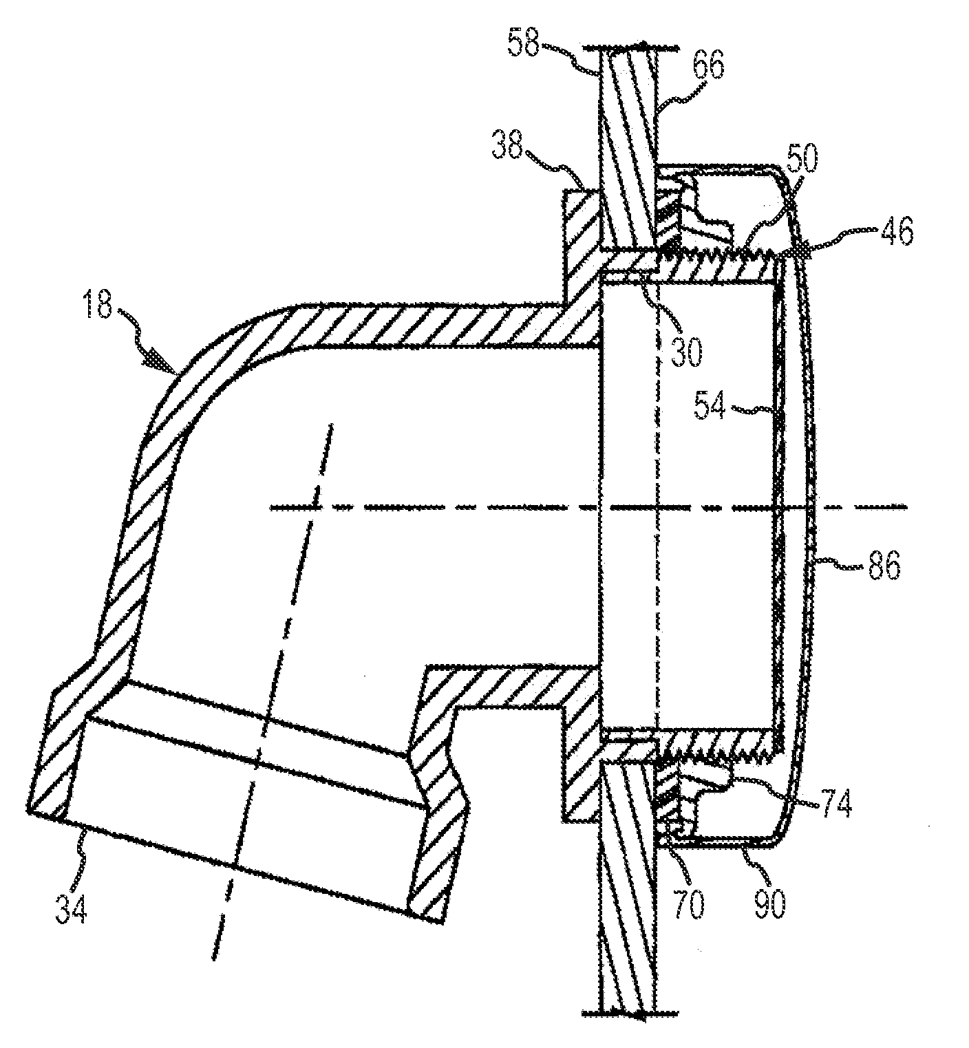
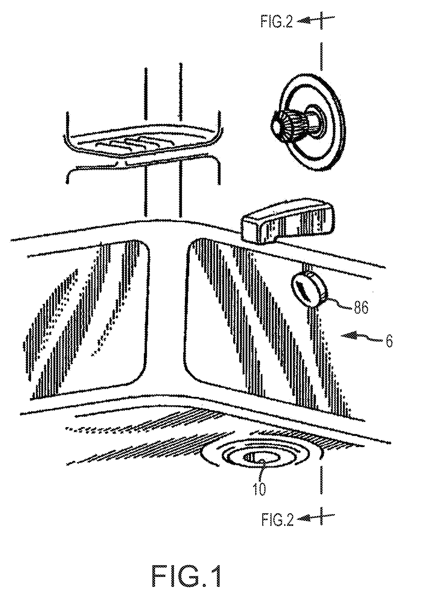
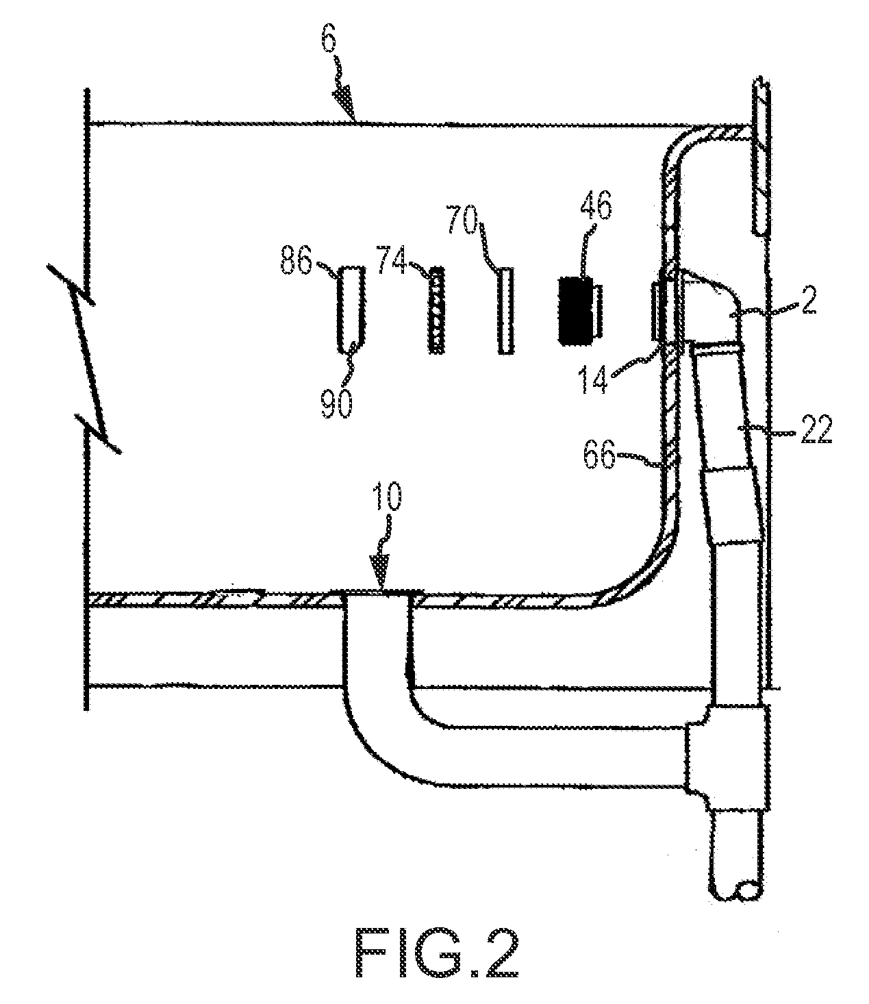
[0047]Referring now to FIGS. 1-9 an overflow assembly 2 adapted for interconnection to a bathtub 6 is provided. The overflow assembly 2 is adapted to be used in conjunction with a bathtub 6 having a drain port 10 and an overflow port 14. The overflow port 14 receives an L shaped elbow 18 that leads into an overflow pipe 22 that eventually feeds into a tee-connector 26. The tee-connector 26 also receives fluid from the drain port 10 of the bathtub 6 and has an opening that connects to the sewer system of the structure.

[0048]Turning now specifically to FIGS. 2-4, an overflow assembly of one embodiment of the present invention is provided. Here, the elbow 18 includes a first end 30 and a second end 34 wherein a flange 38 is spaced from the first end 30. Thus, the first end 30 comprises a lip that protrudes from the flange 38. The first end 30 is adapted to receive a shoulder 42 of a cylindrical fitting 46 that also includes an outer surface with a plurality of threads 50 and may have a...


PUM


Abstract

A system is provided for enhancing the interconnectability of a bathtub to a plumbing system. More specifically, provided is a flexible conduit and an overflow assembly that allows for a portion of the overflow assembly to be easily located with the wall of a bathtub. The flexible conduit provided allows for adjustability of the conduit to the openings of the bathtub. In addition, provided are methods and apparatus that facilitate testing of a plumbing assembly. Finally, an apparatus and methods are provided that protect portions of the finished bathtub assembly to decrease in the need for replacing said hardware. It is envisioned that aspects and inventions disclosed herein can be used in conjunction to facilitate the interconnection and protection of hardware associated with a bathtub.

Description

CROSS REFERENCE TO RELATED APPLICATIONS[0001]This application is a Continuation of U.S. patent application Ser. No. 11 / 931,681, filed Oct. 31, 2007, which is a Continuation-In-Part of abandoned U.S. patent application Ser. No. 10 / 674,862, filed Sep. 30, 2003, which is a Continuation-In-Part of U.S. patent application Ser. No. 10 / 222,062, now U.S. Pat. No. 6,637,050, filed Aug. 16, 2003 and a Continuation-In-Part of U.S. patent application Ser. No. 10 / 229,533, now U.S. Pat. No. 6,675,406, filed Aug. 28, 2002, which is a Continuation of abandoned U.S. patent application Ser. No. 09 / 593,724, filed Jun. 13, 2000. This application is a Continuation-In-Part of U.S. patent application Ser. No. 10 / 732,726, filed Dec. 10, 2003, which is a Continuation-In-Part of U.S. patent application Ser. No. 09 / 954,420, now U.S. Pat. No. 6,691,411, filed Sep. 17, 2001. This application is a Continuation-In-Part of abandoned U.S. patent application Ser. No. 10 / 721,694, filed Nov. 25, 2003, which is a Conti...

Claims


Application Information

Patent Timeline
Patent Type & Authority Patents(United States)
IPC IPC(8): E03C1/22
CPCE03C1/24
Inventor BALL, WILLIAM T.
Owner WCM IND INC
Why Eureka
Try Eureka