
Method for manufacturing liquid discharge head

a liquid discharge head and manufacturing method technology, applied in the field of liquid discharge head manufacturing, can solve the problems of narrow material options and small particulate substances sticking near the discharge ports, and achieve the effects of reducing ink mist puddles, reducing substances sticking, and good discharging without random droplets

Inactive Publication Date: 2012-12-04
CANON KK
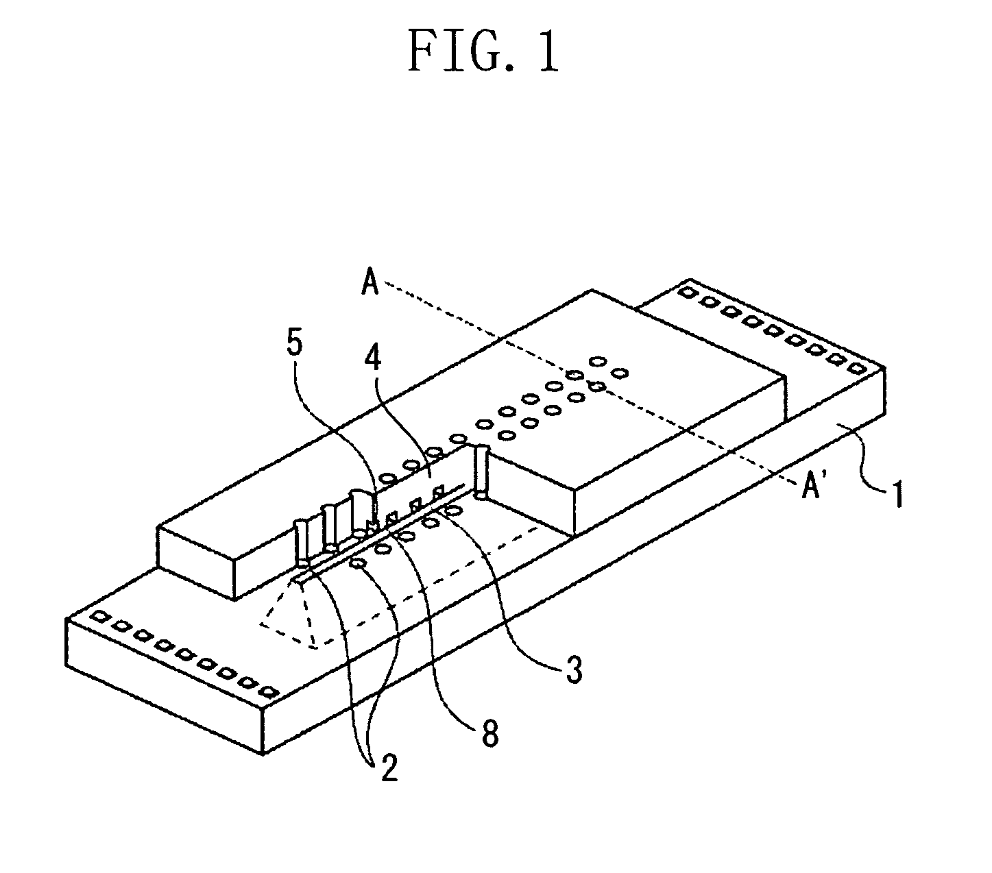
View PDF11 Cites 0 Cited by
  • Summary
  • Abstract
  • Description
  • Claims
  • Application Information

AI Technical Summary

Benefits of technology

The present invention is about an inkjet recording head that can prevent ink from splashing and clogging the nozzle. The invention achieves this by reducing substances that stick to the surface of the nozzle, which prevents puddles of ink from forming. The method involves applying an organic material layer, adding a soluble resin to form a pattern, and then eluting the pattern to create the flow path. The invention can be used with different materials and does not limit the material selection. Overall, the invention improves the efficiency and reliability of inkjet recording.

Problems solved by technology

However, in an inkjet recording head produced experimentally based on the method discussed in U.S. Pat. No. 6,390,606, the present inventors found that depending on diameters of discharge ports and types of inks, discharged droplets were random and did not land on desired impact positions.
It was observed that very small particulate substances were often sticking near the discharge ports.
However, such a change may narrow material options.

Method used


Image

  • Method for manufacturing liquid discharge head
  • Method for manufacturing liquid discharge head
  • Method for manufacturing liquid discharge head

Examples


example 1

[0060]First, a substrate 1 on which an electrothermal converter was disposed as an energy generating element 2 was prepared (FIG. 3A).

[0061]A polyether amide resin (HIMAL 1200 of Hitachi Chemical Co., Ltd., N-methyl-2-pyrrolidone and butyl cellosolve acetate were used as solvents) was applied on the substrate 1 (FIG. 3B).

[0062]The substrate 1 was baked at 100° C. for 30 minutes, and then at 250° C. for 60 minutes to form a film with a thickness of 2 μm.

[0063]A photosensitive positive type resist was applied on the polyether amide organic material 6 by spin-coating, and then patterned to form a photosensitive positive type resist pattern. The polyether amide resin was etched by using the photosensitive positive type resist pattern, and then the photosensitive positive type resist was peeled off to form an organic material layer 7 of the patterned resin (FIG. 3C).

[0064]Polymethyl isopropenyl ketone (ODOUR-1010A of Tokyo Ohka Kogyo Co., Ltd., using cyclohexanone as a solvent) was appli...

example 2

[0083]This example was for improving removability of a substance sticking to a discharge port surface.

[0084]Processes shown in FIGS. 3A to 3C were similar to those of the Example 1.

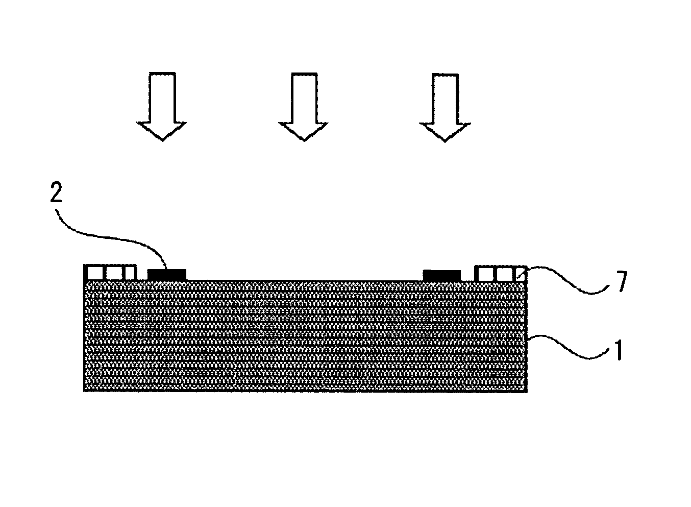
[0085]As shown in FIG. 5, an organic material layer 7 formed on a substrate 1 was irradiated with ultraviolet light. The ultraviolet light was irradiated by the full exposure unit (CE-6000) of Ushio, Inc., which can irradiate with the ultraviolet light having short waves of 300 nm or lower. Irradiation time can be calculated by dividing a designated irradiation amount by a total irradiation intensity value. The total irradiation intensity value is a total value of irradiation intensities automatically measured by the apparatus at each wavelength from 220 nm to 320 nm of ultraviolet light.

[0086]Processes thereafter were similar to those of the Example 1.


PUM

PropertyMeasurementUnit
thicknessaaaaaaaaaa
thicknessaaaaaaaaaa
thicknessaaaaaaaaaa

Abstract

A method for manufacturing a liquid discharge head including a flow path forming member to form a flow path communicating with a discharge port for discharging liquids includes forming an organic material layer on a substrate, applying a soluble resin on the organic material layer to form a resin layer, patterning the resin layer to form a pattern with a shape of the flow path, forming a cover layer as the flow path forming member on the pattern, forming the discharge port to expose a part of the pattern from the cover layer, eluting the pattern from the discharge port to form the flow path, irradiating a substance sticking to a surface of the flow path forming member on which the discharge port is formed with ultraviolet light, wherein the substance contains at least the organic material, and removing the sticking substance.

Description

BACKGROUND OF THE INVENTION[0001]1. Field of the Invention[0002]The present invention relates to a method for manufacturing a liquid discharge head which discharges liquids, and more particularly to a method for manufacturing an inkjet recording head.[0003]2. Description of the Related Art[0004]As an example of a liquid discharge head which discharges liquids, an inkjet recording system for discharging inks to a recording medium to perform recording can be cited.[0005]An inkjet recording head applied to the inkjet recording system (liquid jet recording system) generally includes a plurality of minute discharge ports, liquid flow paths, and energy generating elements disposed in a part of the liquid flow paths to generate energy used for discharging liquids. As a conventional method for manufacturing such an inkjet recording head, for example, U.S. Pat. No. 6,390,606 discusses the following method.[0006]First, an adhesive layer is formed on a substrate having energy generating elemen...

Claims


Application Information

Patent Timeline
Patent Type & Authority Patents(United States)
IPC IPC(8): G01D15/00G11B5/127
CPCB41J2/1603B41J2/1628B41J2/1629B41J2/1631B41J2/1632B41J2/1639B41J2/1645
Inventor TOSHISHIGE, MITSUNORITAGAWA, YOSHINORITAMURA, HIDEOYONEMOTO, TAICHI
Owner CANON KK
Learn More