Communication apparatus and method for data interpolation

a communication apparatus and data interpolation technology, applied in the field of communication apparatuses, communication methods, communication transmission and reception apparatuses, communication transmission and reception methods, etc., can solve the problems of line-based codec and the way data interpolation is to be performed, and achieve the effect of large coding delay, increased demand, and large screen

Inactive Publication Date: 2012-12-04
SONY CORP
View PDF17 Cites 11 Cited by
  • Summary
  • Abstract
  • Description
  • Claims
  • Application Information

AI Technical Summary

Benefits of technology

[0031]3) When the codec rate is changed, it is necessary to perform rate changing processing at a high speed so as to prevent the user from coming under stress. However, when clipping is performed to magnify or reduce an effective screen size, the clock frequency of a clock input when a codec operation is performed may be changed. Thus, for variable clocks, a method for causing the rate changing processing to be less noticeable by the user is desired.
[0032]4) There is a problem relating to a reduction in an interpolation memory. The use of line-based codec significantly reduces the amount of memory necessary for image compression. Although an interpolation memory is necessary in terms of the reliability of the system, it is desirable not to provide an additional memory.
[0034]6) An appropriate countermeasure is to be taken in a case where image quality is markedly changed, for example, a scene change of a moving image. Since line-based codec efficiently deals with information between frames, as in MPEG 2, there are a smaller number of setting parameters exchanged between frames. Thus, in an environment, such as a scene change or channel switching of a moving image, in which image quality is changed significantly in the time axis, the image quality may be visually deteriorated.
[0044]When the amount of audio data exceeds the audio-data threshold, muting may be performed such that a deterioration is less noticeable even when muting is executed in a short period of time.

Problems solved by technology

However, there are many problems with systems using line-based codec.
Thus, since decoded image data for the previous field is not stored in a coder / decoder, a problem related to how data interpolation is to be performed occurs.

Method used


Image

  • Communication apparatus and method for data interpolation
  • Communication apparatus and method for data interpolation
  • Communication apparatus and method for data interpolation

Examples


Embodiment Construction

[0077]Embodiments of the present invention will be described with reference to the drawings.

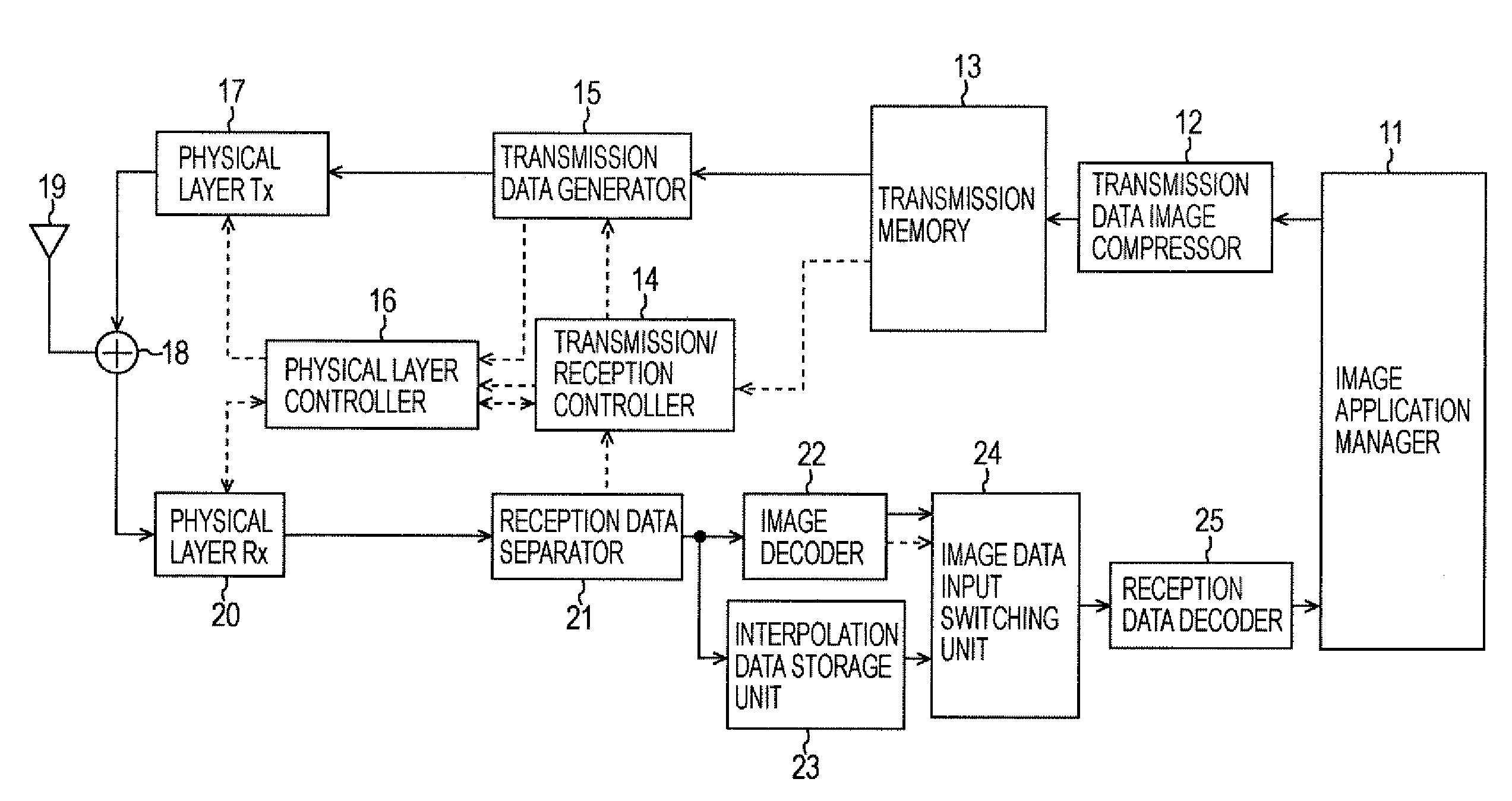
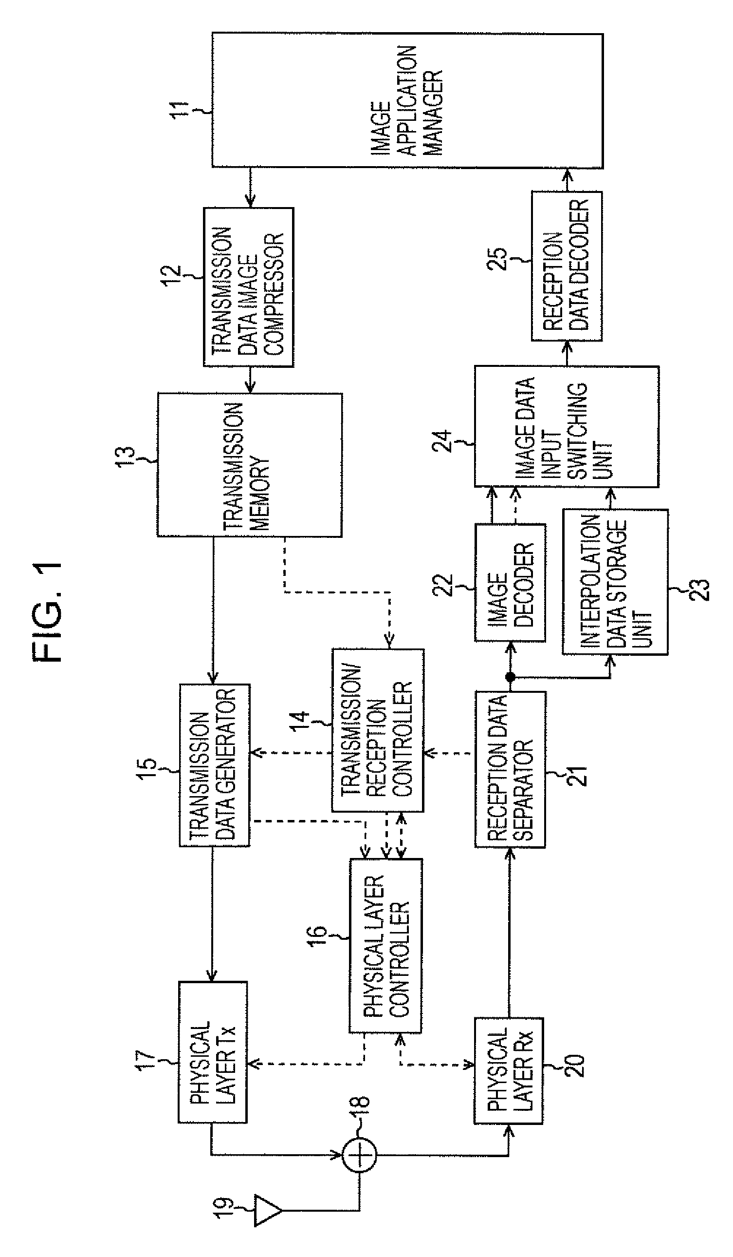
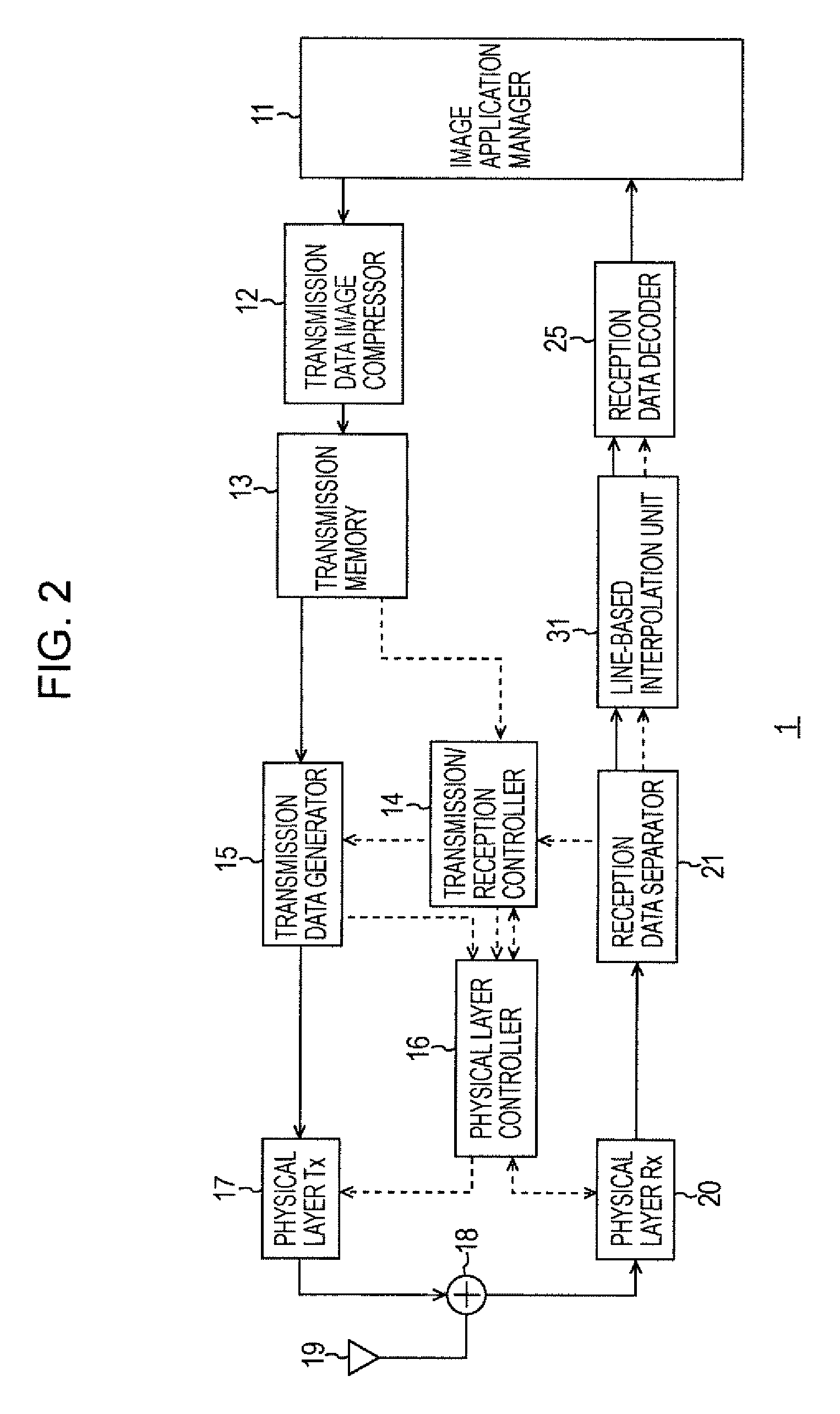
[0078]FIG. 2 is a block diagram showing an example of a configuration of a communication terminal apparatus 1 according to an embodiment of the present invention. Component parts corresponding to component parts in the configuration of the related art are referred to with the same reference numerals and the descriptions of those same component parts will be omitted.

[0079]A line-based interpolation unit 31 performs interpolation processing that is specialized for line-based codec. The term “line-based codec” means image compression in which an image for one field is divided into a plurality of groups each including N lines (N≧1) and image compression is performed for each group (hereinafter, referred to as a line block), thus reducing a delay time.

[0080]A reception data decoder 25 decodes data supplied from an image data input switching unit 44, which will be described with reference to FIG. 3...


PUM


Abstract

A communication apparatus dividing an image for one field into a plurality of groups each including N lines (N≧1) and performing compression / decompression for each group includes a separator separating image data from reception data; a determination unit determining whether an error exists in the separated image data; a storage unit storing the image data as interpolation data when the determination unit determines that no error exists in the image data; a decoder decoding the image data; a first detection unit detecting a decoding position of the image data and a corresponding position of the interpolation data stored in the storage unit when the determination unit determines that an error exists in the image data and that the amount of missing data of the image data exceeds a threshold; and a reading unit reading the interpolation data in accordance with the detected decoding position and corresponding position.

Description

CROSS REFERENCES TO RELATED APPLICATIONS[0001]The present invention contains subject matter related to Japanese Patent Application JP 2006-137133 filed in the Japanese Patent Office on May 17, 2006, the entire contents of which are incorporated herein by reference.BACKGROUND OF THE INVENTION[0002]1. Field of the Invention[0003]The present invention relates to communication apparatuses, communication methods, communication transmission and reception apparatuses, communication transmission and reception methods, and programs, and more particularly, to a communication apparatus, a communication method, a communication transmission and reception apparatus, a communication transmission and reception method, and a program that can be used suitably when image compression is performed for each of a plurality of line blocks.[0004]2. Description of the Related Art[0005]Currently, data is transferred using various types of communication, such as Internet communication. In particular, image dat...

Claims


Application Information

Patent Timeline
Patent Type & Authority Patents(United States)
IPC IPC(8): H04N7/12H04L1/00H04N7/173H04N19/102H04N19/00H04N19/132H04N19/142H04N19/166H04N19/174H04N19/196H04N19/33H04N19/59H04N19/635H04N19/65H04N19/67H04N19/70H04N19/80H04N19/87H04N19/89H04N19/895H04N21/23H04N21/234
CPCH04N21/643H04N19/63H04N19/587H04N19/166H04N19/115
Inventor IWAMI, HIDEKIFUTENMA, SATOSHI
Owner SONY CORP
Why Eureka
Try Eureka