Unlock instant, AI-driven research and patent intelligence for your innovation.

Engine control device

a control device and engine technology, applied in the direction of electric control, ignition automatic control, instruments, etc., can solve problems such as increasing errors, and achieve the effects of preventing combustion deterioration, optimal torque control, and improving fuel efficiency

Active Publication Date: 2012-12-04
HITACHI ASTEMO LTD
View PDF6 Cites 3 Cited by
  • Summary
  • Abstract
  • Description
  • Claims
  • Application Information

AI Technical Summary

Benefits of technology

The present invention provides an engine control device that can accurately calculate compensation coefficients for transient compensation of ignition timing without involving a complicated and large-scale calculation model. The device uses a variable valve timing mechanism capable of changing the phase of intake and / or exhaust valves, calculates an angular difference between the current real phase of the intake / exhaust valve and the target phase, and calculates a compensation coefficient for matching the shift amount or its correlation value with the angular difference. The compensation coefficient is then used to perform transient compensation of the ignition timing. The device can prevent combustion deterioration and torque down due to an excessive advance angle or retard angle of the intake / exhaust valve at a transition time, and improve fuel efficiency. The use of an approximate expression and sensitivity, transition width, and transition interval settings can further reduce errors and improve combustion characteristics.

Problems solved by technology

Therefore, unfortunately, the use of a chemical change as internal state variables involves a complicated calculation and thus may increase an error.

Method used


Image

  • Engine control device
  • Engine control device
  • Engine control device

Examples


Embodiment Construction

[0055]Hereinafter, embodiments of the present invention will be described by referring to the accompanying drawings.

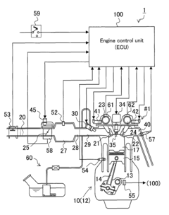
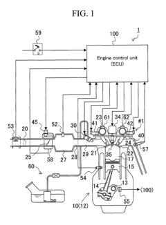
[0056]FIG. 1 is a schematic configuration view illustrating an embodiment (first embodiment) of a control device according to the present invention as well as an example of a vehicle-mounted engine to which the same is applied.

[0057]In FIG. 1, an engine 10 to which a control device 1 of the present embodiment is applied is a spark-ignition multi-cylinder gasoline engine having, for example, four cylinders #1, #2, #3, and #4 (in the figure, #1 is illustrated as a representative example). The engine 10 includes a cylinder 12 having a cylinder head and a cylinder block; and a piston 15 slidably inserted into each cylinder #1, #2, #3, and #4 of the cylinder 12. The piston 15 is coupled to a crankshaft 13 via a con rod 14. Above the piston 15, a combustion operating chamber 17 having a combustion chamber (ceiling or roof portion) with a predetermined shape is defined. A spa...


PUM


Abstract

There is provided an engine control device which can accurately calculate a compensation coefficient used for transient compensation of an ignition timing without involving a complicated and large-scale calculation model in order to prevent a combustion deterioration and the like caused by a mechanical response delay and the like of the variable valve timing mechanism at a transition time such as an acceleration / deceleration time. The angular difference between each current real phase of the intake / exhaust valves 21 and 22 and a target phase set based on an engine load equivalent amount such as an intake air amount is obtained; the shift amount or its correlation value between a current real intake air amount and a theoretical intake air amount value calculated using a pressure inside an intake manifold when each phase of the intake / exhaust valves has reached the target phase is obtained; further a compensation coefficient for matching the shift amount or its correlation value with the angular difference is obtained; and the compensation coefficient is used to perform transient compensation of an ignition timing.

Description

BACKGROUND OF THE INVENTION[0001]1. Field of the Invention[0002]The present invention relates to an engine control device having a variable valve timing (VVT) mechanism capable of changing a phase of an intake valve and / or an exhaust valve, and particularly to an engine control device configured to be able to prevent a combustion deterioration, a torque reduction, and the like caused by a mechanical response delay and an overshoot of the variable valve timing mechanism at a transition time such as an acceleration / deceleration time.[0003]2. Background Art[0004]For example, as disclosed in JP Patent Publication (Kokai) No. 8-261026A (1996), conventionally there has been used a variable valve timing mechanism capable of changing a phase of an intake valve and / or an exhaust valve (hereinafter also referred to simply as an intake / exhaust valve) in order to change a degree of overlap between an opening timing of the intake valve and a closing timing of the exhaust valve according to an en...

Claims


Application Information

Patent Timeline
Patent Type & Authority Patents(United States)
IPC IPC(8): F02D41/04F02P5/04F02D13/02F01L1/34
CPCF02D13/0219F02D41/0002F02D41/18F02P5/1504F02D2041/001F02D2200/0402F02D2200/0408Y02T10/46Y02T10/42Y02T10/18F02M25/0752F02M26/01Y02T10/12Y02T10/40
Inventor ASANO, SEIJIKIMURA, SHINGOKOTABE, KENICHIMIZUSHIMA, KENJISUZUKI, KUNIHIKO
Owner HITACHI ASTEMO LTD