Electrostatic capacitive vibrating sensor

a capacitive vibration and capacitive technology, applied in the direction of instruments, fluid tightness measurement, specific gravity measurement, etc., can solve the problems of clogging of the vent hole, and reducing etc., to achieve the effect of reducing the acoustic resistance of the ventilation pathway passing through the vent hole, reducing the dust-proof property, and reducing the noise resistan

Active Publication Date: 2012-12-11
MMI SEMICON CO LTD
View PDF48 Cites 40 Cited by
  • Summary
  • Abstract
  • Description
  • Claims
  • Application Information

AI Technical Summary

Benefits of technology

[0048]One or more embodiments of the invention provides a vibration sensor that can solve the contradictory problem. That is, in the contradictory problem, because the acoustic resistance of the ventilation pathway passing through the vent hole is decreased when the opening area of the acoustic hole is enlarged, the low-frequency characteristic of the vibration sensor is lowered or the vent hole clogs easily by the dust to lower the dust-proof property. On the other hand, when the opening area of the acoustic hole is reduced, the damping suppression effect of the vibrating electrode plate is degraded to lower the high-frequency characteristic of the vibration sensor, the fixed electrode plate is easily subjected to the sound pressure to lower the sensor accuracy, the sticking of the electrode plates is easily generated, or the noise generated by the thermal noise is increased in the air gap.

Problems solved by technology

That is, in the contradictory problem, because the acoustic resistance of the ventilation pathway passing through the vent hole is decreased when the opening area of the acoustic hole is enlarged, the low-frequency characteristic of the vibration sensor is lowered or the vent hole clogs easily by the dust to lower the dust-proof property.
On the other hand, when the opening area of the acoustic hole is reduced, the damping suppression effect of the vibrating electrode plate is degraded to lower the high-frequency characteristic of the vibration sensor, the fixed electrode plate is easily subjected to the sound pressure to lower the sensor accuracy, the sticking of the electrode plates is easily generated, or the noise generated by the thermal noise is increased in the air gap.

Method used


Image

  • Electrostatic capacitive vibrating sensor
  • Electrostatic capacitive vibrating sensor
  • Electrostatic capacitive vibrating sensor

Examples


first embodiment

[0093](First Embodiment)

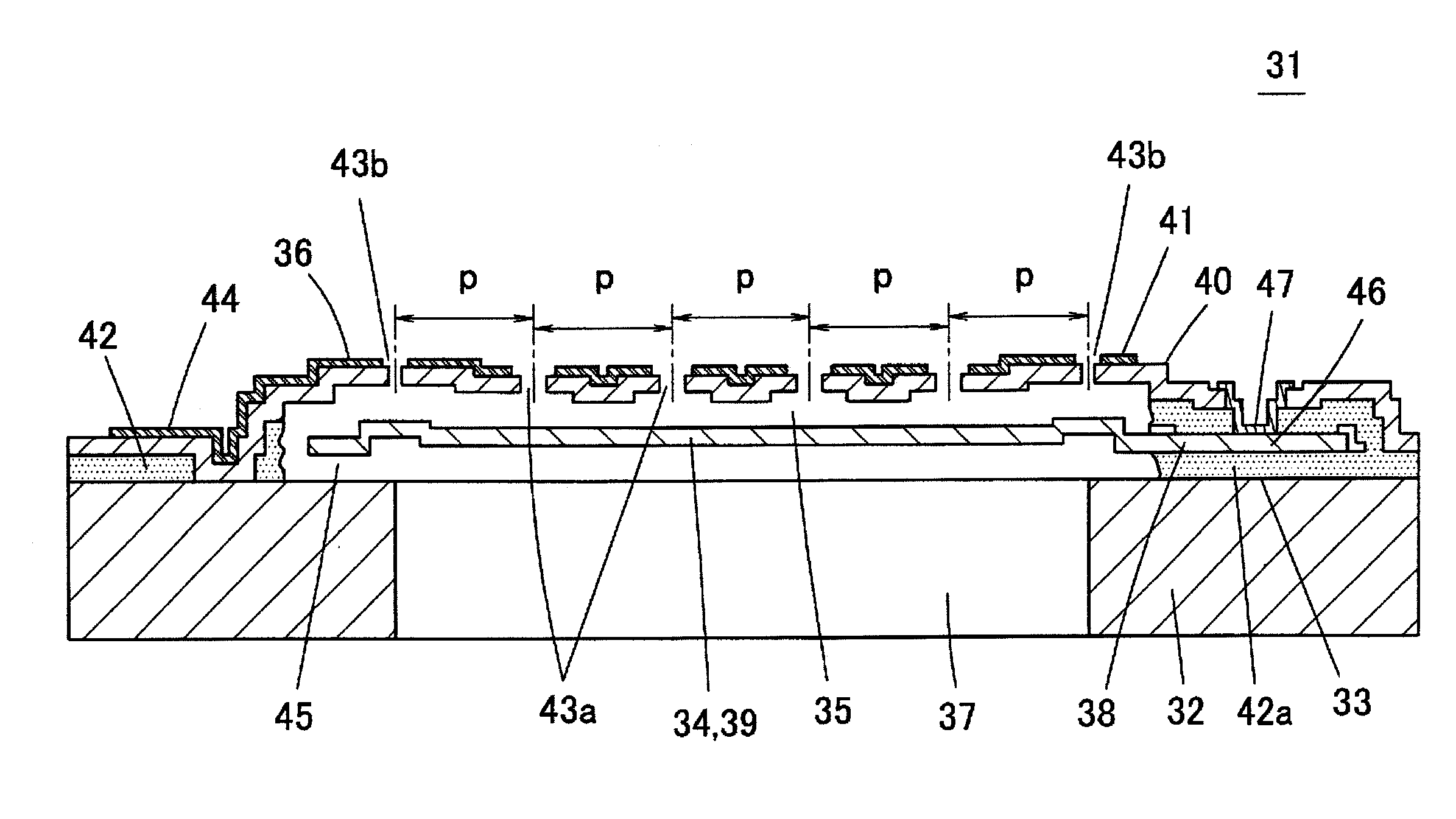
[0094]A first embodiment of the invention will be described with reference to FIGS. 6 to 12. FIG. 6 is a schematic sectional view illustrating an electrostatic capacitive vibration sensor 31 of the first embodiment, the right half of FIG. 6 illustrates a section passing through a fixed portion of a vibrating electrode plate, and the left half illustrates a section passing between the fixed portions. FIG. 7 is an exploded perspective view of the vibration sensor 31, FIG. 8 is a plan view of the vibration sensor 31, and FIG. 9 is a plan view illustrating a state in which the fixed electrode plate in an upper surface of the vibration sensor 31 is removed.

[0095]The vibration sensor 31 is an electrostatic capacitive sensor, in which a vibrating electrode plate 34 is provided in an upper surface of a silicon substrate 32 with an insulating coating 33 interposed therebetween, and a fixed electrode plate 36 is provided on the vibrating electrode plate 34 with a micro...

second embodiment

[0133](Second Embodiment)

[0134]FIG. 16 is a plan view illustrating a vibration sensor 51 according to a second embodiment of the invention. FIG. 17 is a plan view of a state in which a fixed electrode film of the vibration sensor 51 is removed. In the vibration sensor 51, a portion above the through-hole 37 of the silicon substrate 32 is covered with the vibrating electrode plate 34, and the outer peripheral portion of the vibrating electrode plate 34 is partially fixed to the upper surface of the silicon substrate 32. In the vibrating electrode plate 34, a region (fixed portion 38) fixed to the upper surface of the silicon substrate 32 by the retaining portion 42a formed by the sacrifice layer 42 of the upper surface of the silicon substrate 32 is expressed by a hatched line in FIG. 17. Plural slits 52 are opened in positions near the outer peripheral portion inside the outer peripheral portion fixed to the silicon substrate 32. The outer peripheral portion of the vibrating electro...

third embodiment

[0138](Third Embodiment)

[0139]FIG. 18(a) is a plan view illustrating a vibration sensor 61 according to a third embodiment of the invention, and FIG. 18(b) is a schematic sectional view of the vibration sensor 61. In the first and second embodiments, the vibrating electrode plate 34 and the fixed electrode plate 36 are formed in order on the silicon substrate 32. As illustrated in FIG. 18, the fixed electrode plate 36 and the vibrating electrode plate 34 may be formed in order on the silicon substrate 32. Because other structures are similar to those of the first embodiment, the description is omitted. In the third embodiment, the acoustic vibration propagating from the through-hole 37 of the silicon substrate 32 propagates to the vibrating electrode plate 34 through the acoustic holes 43a and 43b, and the vibrating electrode plate 34 is vibrated by the acoustic vibration.


PUM


Abstract

An electrostatic capacitive vibration sensor has a substrate, a through-hole, a vibrating electrode plate, and a fixed electrode plate opposite the vibrating electrode plate. The fixed electrode plate is subjected to vibration to perform membrane oscillation. Pluralities of acoustic holes are made in the fixed electrode plate. The vibrating and fixed electrode plate are disposed on a surface side of the substrate such that an opening on the surface side of the through-hole is covered. A lower surface of an outer peripheral portion of the vibrating electrode plate is partially fixed to the substrate. A vent hole that communicates a surface side and a rear surface side of the vibrating electrode plate is made between the surface of the substrate and the lower surface of the vibrating electrode plate. In addition, the acoustic hole has a smaller opening area except at the outer peripheral portion.

Description

TECHNICAL FIELD[0001]The present invention relates to an electrostatic capacitive vibration sensor, particularly to a micro-size vibration sensor that is produced by utilizing a MEMS (Micro Electro Mechanical System) technology or a micromachining technology.BACKGROUND ART[0002]FIG. 1 illustrates a basic structure of the electrostatic capacitive vibration sensor. In a vibration sensor 11, a vibrating electrode plate 13 is disposed in an upper surface of a substrate 12 whose central portion is opened, an upper portion of the vibrating electrode plate 13 is covered with a fixed electrode plate 14, and plural acoustic holes 15 are made in the fixed electrode plate 14. When an acoustic vibration 16 propagates toward the vibration sensor 11, the acoustic vibration 16 vibrates the vibrating electrode plate 13 through the acoustic holes 15. Because a distance between the vibrating electrode plate 13 and the fixed electrode plate 14 changes when the vibrating electrode plate 13 is vibrated,...

Claims


Application Information

Patent Timeline
Patent Type & Authority Patents(United States)
IPC IPC(8): G01M3/32
CPCH04R19/005H04R2201/003H04R19/04
Inventor KASAI, TAKASHIONO, KAZUYUKITSURUKAME, YOSHITAKA
Owner MMI SEMICON CO LTD
Why Eureka
Try Eureka