Methods for manufacturing thin film transistor array substrate and display panel

Active Publication Date: 2012-12-11
TCL CHINA STAR OPTOELECTRONICS TECH CO LTD
View PDF7 Cites 1 Cited by
  • Summary
  • Abstract
  • Description
  • Claims
  • Application Information

AI Technical Summary

Benefits of technology

[0015]The methods of the present invention for manufacturing the TFT array substrate and the display panel can reduce an amount of the required masks in the fabrication process, hence reducing the cost and time of the fabrication process. The method of the present invention can reduce the using of wet etching, thereby alleviating the effect of the wet etching on the elements of the TFT array substrate. Moreover, the method of the present can use a normal mask for manufacturing without using a multi tone mask, thereby greatly reducing the process cost.

Problems solved by technology

However, the masks are very expensive.
For this reason, the more an amount of the masks is, the higher a cost for fabricating the TFT is.
Furthermore, more masks will result in longer process time and more complicated process.
Besides, in the photolithography process, several steps of wet etching are required, hence deteriorating metal lines of the TFT array substrate

Method used


Image

  • Methods for manufacturing thin film transistor array substrate and display panel
  • Methods for manufacturing thin film transistor array substrate and display panel
  • Methods for manufacturing thin film transistor array substrate and display panel

Examples


Embodiment Construction

[0019]The following embodiments are referring to the accompanying drawings for exemplifying specific performable embodiments of the present invention. Furthermore, directional terms described by the present invention, such as upper, lower, front, back, left, right, inner, outer, side and etc., are only directions by referring to the accompanying drawings, and thus the used directional terms are used to describe and understand the present invention, but the present invention is not limited thereto.

[0020]In the drawings, structure-like elements are labeled with like reference numerals.

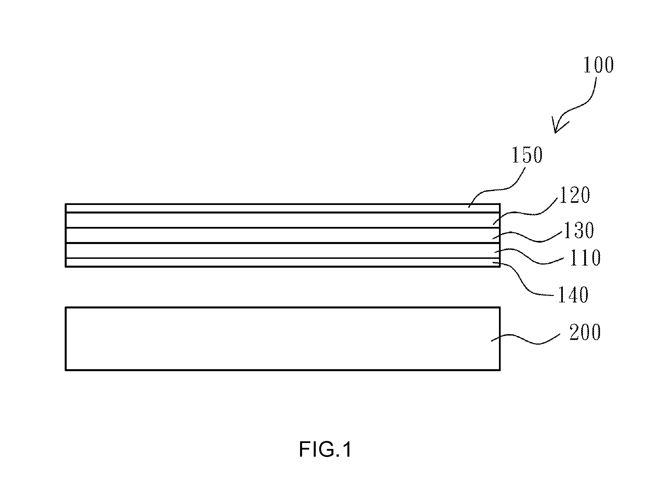
[0021]Referring to FIG. 1, a cross-sectional view showing a display panel and a backlight module according to an embodiment of the present invention is illustrated. The method of the present embodiment for manufacturing a TFT array substrate can be applicable to the fabrication of the display panel 100, such as a liquid crystal display panel. When utilizing the display panel 100 of the present embodiment...


PUM


Abstract

The present invention provides methods for manufacturing a thin film transistor (TFT) array substrate and a display panel. The method for manufacturing the TFT array substrate comprises the following steps: forming a plurality of gate electrodes, a gate insulating layer, a semiconductor layer, an ohmic contact layer, an electrode layer and a first photo-resist layer on a transparent substrate in sequence; patterning the first photo-resist layer; etching the ohmic contact layer and the electrode layer; coating a second photo-resist layer on the patterned first photo-resist layer and in the channels; removing the second photo-resist layer on the patterned first photo-resist layer and to allow the second photo-resist layer in the channels to remain therein; etching the semiconductor layer; removing the patterned first photo-resist layer and the second photo-resist layer; forming a passivation layer on the channels, the source electrodes and the drain electrodes; and forming a pixel electrode layer on the passivation layer. The present invention can reduce an amount of the required masks in the fabrication process, and only one wet etching is required to etch the metal material on the TFT array substrate.

Description

FIELD OF THE INVENTION[0001]The present invention relates to a field of a liquid crystal display technology, and more particularly to methods for manufacturing a thin film transistor (TFT) array substrate and a display panel.BACKGROUND OF THE INVENTION[0002]Liquid crystal displays (LCDs) have been widely applied in electrical products. Currently, most of LCDs are backlight type LCDs which comprise a liquid crystal panel and a backlight module. In general, the LCD panel may include a color filter (CF) substrate and a TFT array substrate. The CF substrate includes a plurality of color filters and a common electrode. The TFT array substrate includes a plurality of parallel scanning lines, a plurality of parallel data lines, a plurality of TFTs and a plurality of pixel electrodes. The scanning lines are respectively vertical to the data lines. Each adjacent two of the scanning lines and each adjacent two of the data lines intersect to define a pixel area.[0003]In a process for fabricati...

Claims


Application Information

Patent Timeline
IPC IPC(8): H01L21/00H01L21/84H01L21/8238H01L21/469
CPCH01L29/66765H01L21/32139H01L27/1288
Inventor XUE, JING-FENGHSU, JEHAOYAO, XIAOHUI
Owner TCL CHINA STAR OPTOELECTRONICS TECH CO LTD
Why Eureka
Try Eureka