Motor

a brushed dc motor and motor current technology, applied in the direction of dynamo-electric machines, dc commutators, electrical apparatus, etc., can solve the problems of inability to generate a sufficiently high pulse voltage for detection, difficulty in reliably detecting pulses, and so as to avoid an increase in mechanical noise and vibration, the effect of easy detection

Inactive Publication Date: 2012-12-11
MABUCHI MOTOR
View PDF12 Cites 2 Cited by
  • Summary
  • Abstract
  • Description
  • Claims
  • Application Information

AI Technical Summary

Benefits of technology

[0016]According to the present invention, in a brushed DC motor having four or more field poles, the centers of mutually facing magnetic poles are aligned with each other to thereby avoid an increase in mechanical noise and vibration, and a shift of brush changeover timing enables the generation of a current waveform from which rotation can be readily detected without need to use a special detection apparatus.

Problems solved by technology

In this manner, the illustrated circuit can yield the number of pulses proportional to the rotational speed of the motor through time differential of the pulse voltage appearing across the current detection resistor R. However, when motor current smoothly varies periodically, pulses cannot be detected from the motor current.
Particularly, in a motor having four or more field poles, difficulty is encountered in reliably detecting pulses whose magnitude sufficiently exceeds a threshold value, from current flowing through the current detection resistor.
However, merely through employment of difference in magnetic flux density among the magnets, there cannot be generated a sufficiently high pulse voltage for detection by such a pulse detection circuit as described in Patent Document 1 mentioned above.Patent Document 1: Japanese Patent Application Laid-Open (kokai) No. 2004-297861Patent Document 2: Japanese Patent Application Laid-Open (kokai) No.

Method used


Image

  • Motor
  • Motor
  • Motor

Examples


Embodiment Construction

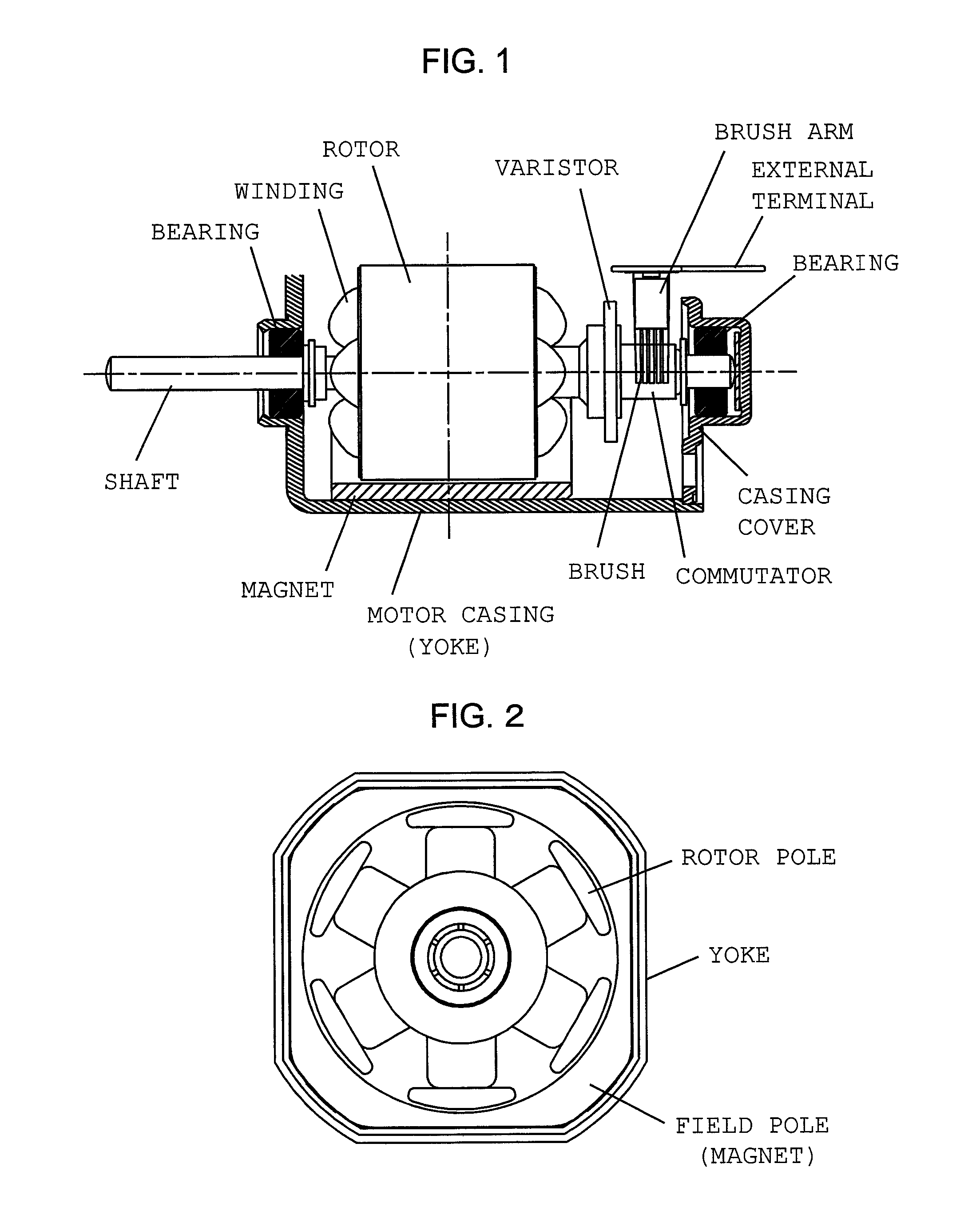
[0028]The present invention will next be described by way of example. FIG. 1 is a longitudinal, partially sectional view showing the configuration of a small motor having a quadrangular external shape which embodies the present invention. FIG. 2 is a side view of the motor shown in FIG. 1 as viewed from the commutator side with a casing cover removed. A small motor having a quadrangular (square) external shape and having a 4-pole field magnet and six rotor poles will be described below. However, the present invention can be applied to a small motor having four or more field poles and three or more rotor poles. The small motor can have other external shapes, such as a circular external shape.

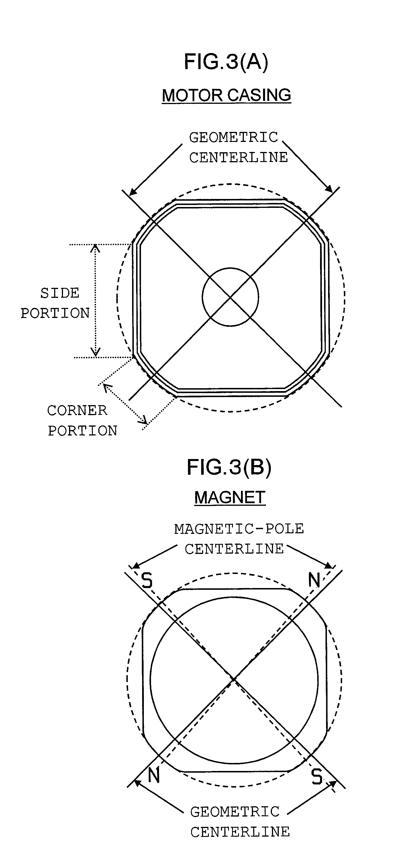
[0029]As illustrated, a magnet which serves as field poles is attached to the inner peripheral surface of a motor casing. The motor casing is formed from a metallic material into a closed-bottomed tubular shape by press working. A quadrangular side of the motor casing made of metal and having a s...


PUM


Abstract

Magnetic poles are arranged such that the N pole and the S pole alternate in a circumferential direction. Two N poles face each other with an interval of 180° therebetween, and two S poles face each other with an interval of 180° therebetween. Each of the magnetization center of a North magnetic pole and the magnetization center of a South magnetic pole is positionally shifted from the center position between the magnetization centers of two magnetic poles of the other polarity located on opposite sides of the North or South magnetic pole. The magnetization centers of the magnetic poles are disposed in such a manner as to be positionally shifted from geometric centerlines. Brushes are disposed along the respective geometric centerlines. The magnetization centers of two adjacent magnetic poles are positionally shifted toward or away from each other by the same shift angle α with respect to the respective geometric centerlines.

Description

TECHNICAL FIELD[0001]The present invention relates to a brushed DC motor having four or more field poles and capable of generating sufficiently large motor current pulses for detecting the rotational speed of the motor from the waveform of current flowing through the motor.BACKGROUND ART[0002]Conventionally, there is known an apparatus which detects the rotational speed of a brushed DC motor from the waveform of current flowing through the motor without need to use an encoder, a tachogenerator, or the like (refer to Patent Documents 1 and 2).[0003]FIG. 9 shows the conventional pulse detection circuit which is described in Patent Document 1 and adapted to detect rotation pulses generated in association with rotation of a motor. The pulse detection circuit detects through current which flows to the motor from a current detection resistor R connected to the ground side of a motor driver, thereby detecting through current pulses generated in association with rotation of the motor.[0004]...

Claims


Application Information

Patent Timeline
Patent Type & Authority Patents(United States)
IPC IPC(8): H02K21/26
CPCH02K11/026H02K23/04H02K13/10
Inventor UENISHI, EIJIMAYUMI, EIJI
Owner MABUCHI MOTOR
Why Eureka
Try Eureka