Power source having a parallel cell topology

a power source and topology technology, applied in the field of electronic devices, can solve the problems of reducing the capacity of the battery, affecting and only using the technique, so as to eliminate reduce the need for cell balancing, and improve the individual control of the cell

Active Publication Date: 2012-12-11
APPLE INC
View PDF2 Cites 8 Cited by
  • Summary
  • Abstract
  • Description
  • Claims
  • Application Information

AI Technical Summary

Benefits of technology

[0013]In another embodiment of the present invention, buck-boost controllers may be used in the power source. The parallel configuration of the cells within the power source may allow for increased individual control of the cells and also may eliminate the need for cell balancing. By eliminating the need for cell balancing, manufacturing tolerances may be relaxed as the cells within a power source need not have similar capacities. Further, the state of charge of the cells within a power source no longer require balancing.
[0014]Additionally, the parallel configuration of the cells and the buck-boost controllers within the power source may allow for greater control of both cell charging and cell discharging. For example, when a cell is discharging and the cell voltage is lower than the required output voltage, the buck-boost controller may enter a boost mode and amplify the voltage to satisfy the load. Also, when a cell is discharging and the cell voltage is higher than the required output voltage, the buck-boost controller may enter a buck mode and reduce the voltage to appropriately supply the load. As another example, when a cell is charging and the output voltage is higher than the cell voltage, the buck-boost controller may enter a reverse buck mode and supply the cell with charging current. The reverse buck mode is similar to the discharging boost mode with the exception that the current flows from the common node to the cell. The individual control of the cells may allow the cells to be fully or substantially charged and discharged, thus maximizing the capacity and runtime of the power source.
[0015]By configuring every cell only in parallel with all the other cells (such that no cell is in series with any other cell), another embodiment may be used for isolating one or more cells from the other cells. The ability to isolate one cell provides a number of advantages. One such advantage may be exemplified by allowing a cell to rest before measuring the open circuit voltage of the cell. Isolating a cell may allow the state of charge of the cell to be calibrated using the open circuit voltage technique without resting the entire power source. Further, periodically isolating cells to measure the open circuit voltage and to calibrate the cell's state of charge constrains the state of charge uncertainty that may grow when using the coulomb counting technique. When a cell is isolated for the state of charge measurement, the cell may be allowed to rest. Cells that are allowed to rest may have increased capacity compared to continually discharging cells.
[0016]Cell isolation may also indirectly yield extended battery runtime, which may result directly from an increase in the amount of charge available. For example, a substantially or fully discharged cell may be isolated from the other cells while the other cells continue to provide power to the output. This may result in the power source providing power until the last cell is depleted, as opposed to only providing power until the first cell is depleted. An additional advantage is the ability to replace individual cells in the power source.
[0017]Furthermore, certain embodiments may allow for greater freedom in power source design and system design. The parallel configuration of the components within the power source may reduce the constraints on cell configurations, thus permitting various cell configurations within the power source. For example, the power source design may contain different sized cells with different cell capacities to fulfill different conditions such as weight requirements, capacity or runtime requirements. Another result of the capability to vary power source configurations may be the location or placement of the power sources within the system itself. For example, the power sources may be configured in different sizes and / or may be used to fill the available space in the system itself. Furthermore, the power sources may be placed non-adjacently within the system.

Problems solved by technology

However, this technique is only useful when the cell is not being charged or discharged.
Consequently, in an environment where a battery is not allowed to rest, the error in the state of charge estimate will be significant.
Failure to equalize or balance the state of charge of individual cells with one another in a battery with cells in series may lead to reduced capacity of the battery.
Batteries with cells that are too far out of balance are typically identified and disabled, leading to lower pack lifetime.
A number of factors contribute to cell imbalance, such as aging characteristic differences of the cells or uneven temperature distribution within the system.
There are a number of disadvantages imposed by cell balancing.

Method used


Image

  • Power source having a parallel cell topology
  • Power source having a parallel cell topology
  • Power source having a parallel cell topology

Examples


embodiment 100

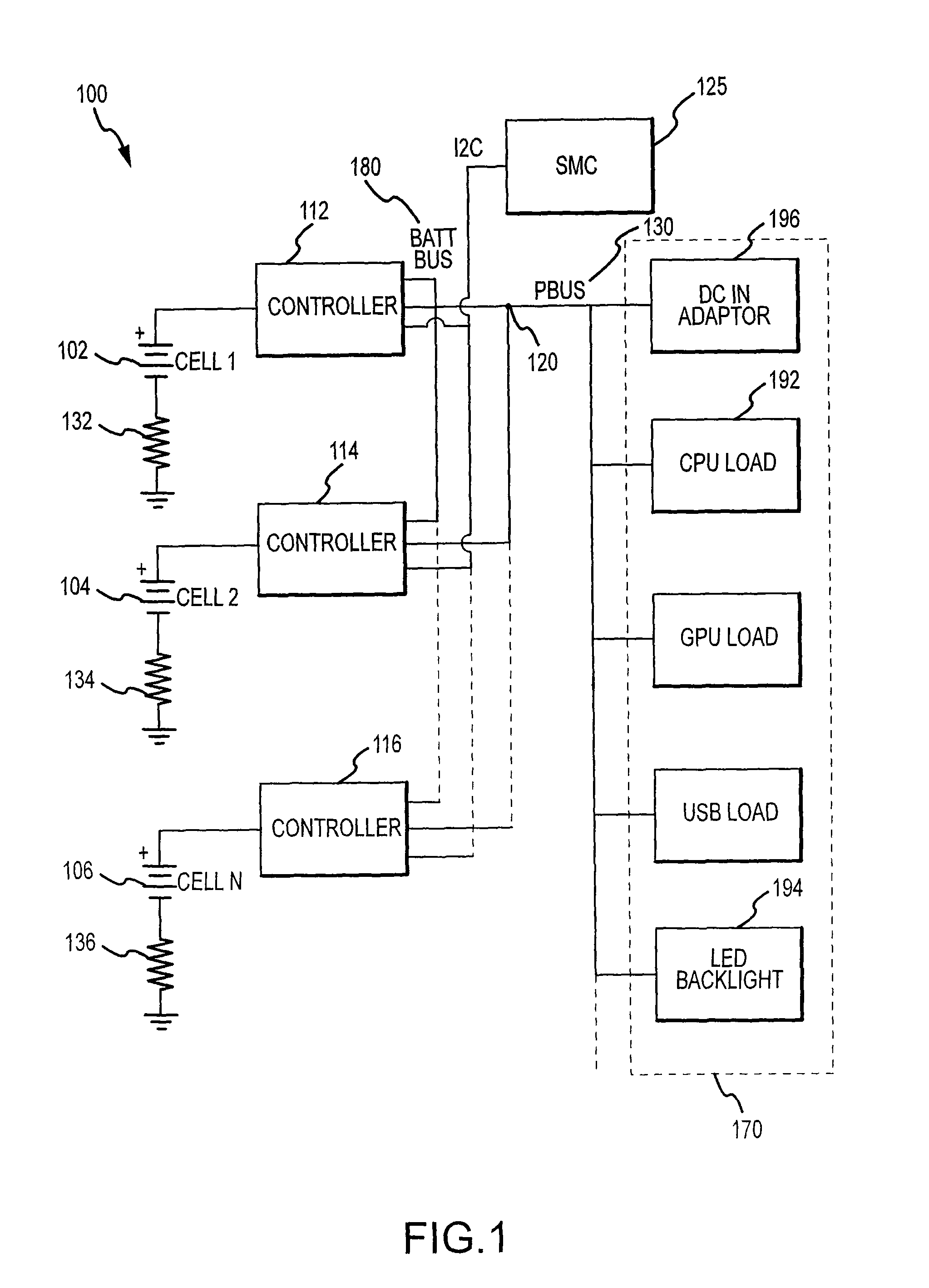
[0034]In embodiment 100, cells 102, 104, 106 may each be operationally or directly connected to individual dedicated controllers. One exemplary embodiment of a controller will be discussed in more detail with respect to FIG. 3, below. In certain embodiments of the present invention, each controller may be a buck-boost controller. For example, in FIG. 1 cell 102 may have a dedicated buck-boost controller 112, while cell 104 may have a second dedicated buck-boost controller 114 and cell 106 may have a third dedicated buck-boost controller 116. The number of buck-boost controllers in FIG. 1 is not intended as a limitation but merely an example for explanatory purposes. Buck-boost controller 112, buck-boost controller 114 and buck-boost controller 116 may be operationally or directly connected in parallel with one another and each of the buck-boost controllers may be operationally or directly connected to a common node 120. The buck-boost controllers 112, 114, 116 may also be operationa...

embodiment 200

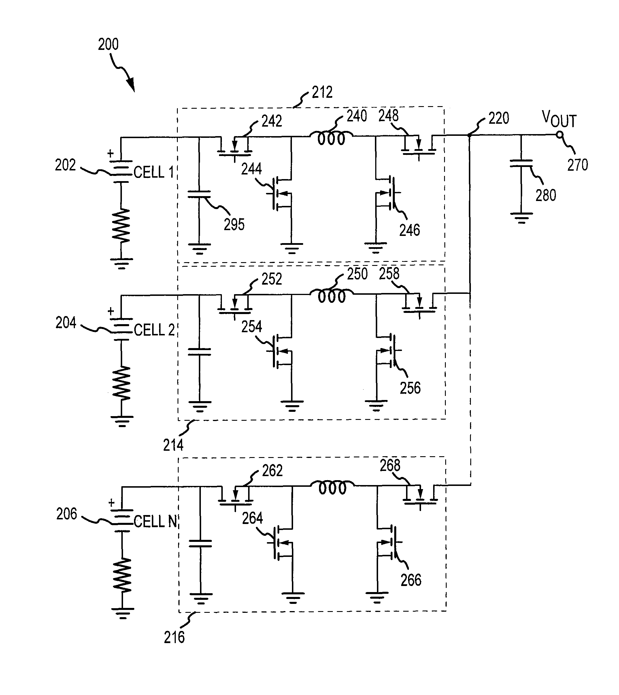
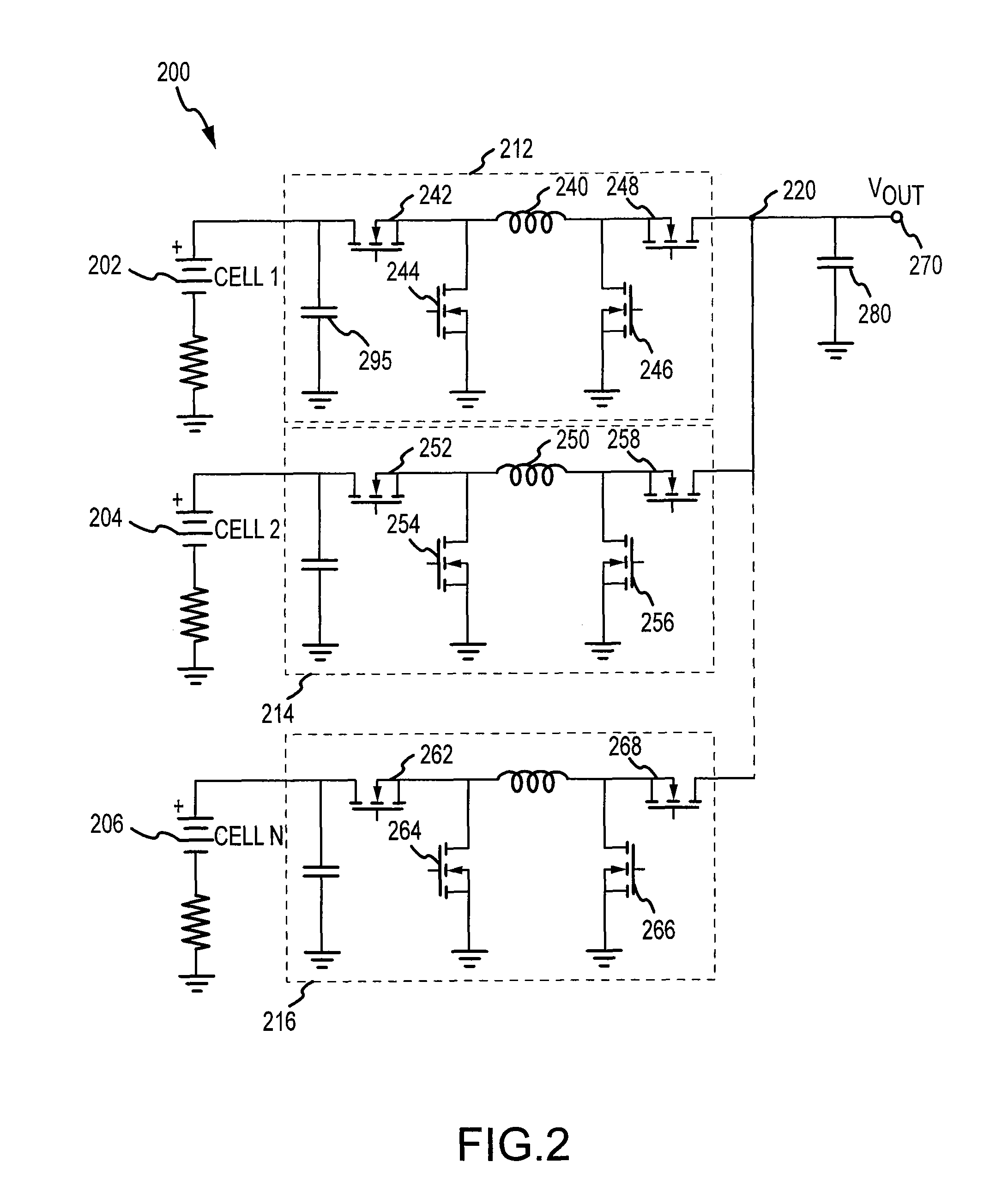
[0047]FIG. 2 depicts a schematic of another exemplary embodiment 200 of the present invention. Similar to FIG. 1, every cell may be operationally or directly connected in parallel with all other cells, thus cell 202 may be operationally or directly connected only in parallel with cells 204 and 206. The embodiment 200 also depicts buck-boost controllers such as buck-boost controllers 212, 214, 216. A buck-boost controller, such as buck-boost controller 212 may have individual elements which include, but are not limited to, field effect transistors (hereinafter “FETs”) 242, 244, 246, 248, inductor 240, capacitor 295 and so forth. The individual buck-boost controllers 212, 214, 216 may each be dedicated to an individual cell of the cells 202, 204, 206 on a one to one basis. The buck-boost controllers 212, 214, 216 as well as the cells 202, 204, 206 may be operationally or directly connected to a common node 220. In one embodiment the common node 220 may be operationally or directly con...

embodiment 300

[0053]FIG. 3 depicts a schematic of another exemplary embodiment 300 including a controller 310. The embodiment 300 may include a buck-boost controller 310. As depicted in FIG. 3, the buck-boost controller 310 may include, but is not limited to, multiple elements such as FET 342, FET 344, FET 346, FET 348, inductor 340 and capacitor 395. Generally, the FETs presented in FIG. 1, FIG. 2 and FIG. 3, are n-channel FETs. Alternative embodiments may use p-channel FETs or any other type of transistor or switch that is appropriate. Also, the figures are not intended to limit the present invention to a particular type of switch or transistor.

[0054]Embodiment 300 may include a FET controller 360. As depicted in FIG. 3, the gates of FET 342, FET 344, FET 346 and FET 348 may be connected to the FET controller 360. The embodiment 300 may also have a cell management unit 350. In one embodiment, cell management unit 350, FET controller 360, FETs 342, 344, 346, 348, inductor 340 and capacitors 390 ...


PUM

PropertyMeasurementUnit
poweraaaaaaaaaa
state of chargeaaaaaaaaaa
charge levelaaaaaaaaaa

Abstract

A power source with multiple cells connected in parallel to a common node or power supply point. The individual cells within the power source may also have a dedicated controller for each of the individual cells. Additionally, a system controller is coupled to each controller in a feedback loop and is configured to selectively connect each cell of the plurality of cells to a power bus to control the discharge of each of the plurality of cells.

Description

CROSS-REFERENCE FOR RELATED APPLICATIONS[0001]This application is a continuation patent application of U.S. patent application Ser. No. 12 / 032,513, filed Feb. 15, 2008 and titled “Power Source Having a Parallel Cell Topology,” the disclosure of which is hereby incorporated herein by reference in its entirety.TECHNICAL FIELD[0002]The present invention generally relates to electronic devices and more specifically to a power source for electronic devices.BACKGROUND DISCUSSION[0003]Many electronic devices use portable power sources such as a cell or a battery. As used herein, the term “cell” refers generally to any power source that may store energy and furnish the stored energy as an electrical voltage and the term “battery” refers generally to multiple cells. Furthermore, cells and batteries may be electrostatic or electrochemical in nature.[0004]Electronic devices are increasingly able to execute multiple functions simultaneously, thereby increasing the power demand of the device and...

Claims


Application Information

Patent Timeline
Patent Type & Authority Patents(United States)
IPC IPC(8): H02J7/00H02J7/04H01M10/36
CPCG06F1/189G06F1/26H01M10/441H02J1/102H02J7/0013H01M10/4207H01M10/052Y10T29/49108B60L3/12B60L2240/545B60L2240/547B60L2240/549B60L58/10B60L58/22H02M3/1582Y02E60/10Y02T10/70B60L3/0046Y02P70/50
Inventor ATHAS, WILLIAMGREENING, THOMAS CHARLESMICHALSKE, STEVEN CHARLES
Owner APPLE INC
Why Eureka
Try Eureka