Image forming apparatus

a technology of image forming apparatus and forming tube, which is applied in the direction of electrographic process apparatus, instruments, optics, etc., can solve the problems of delay in switching power supply ratio, higher cost of apparatus in the case of phase control, and inability to provide appropriate power

Inactive Publication Date: 2012-12-11
CANON KK
View PDF32 Cites 43 Cited by
  • Summary
  • Abstract
  • Description
  • Claims
  • Application Information

AI Technical Summary

Benefits of technology

[0042]The present invention has been made in view of the above-mentioned problems, and has an object of providing a technology of performing power correction at an appropriate timing by reducing the shift between the timing of performing power correction before a recording material enters a heat nip and the timing of a revising cycle of a power supply ratio.

Problems solved by technology

Thus, when the revising cycle is excessively long, switching of the power supply ratio is delayed, disabling supply of appropriate power when necessary.
However, costs of the apparatus are higher in the case of phase control because a noise filter is necessary and a circuit configuration is complex.
In the heating devices of the film-heating type, especially in a device which includes an elastic layer in the heat film, entry of the recording material into a heat nip portion may be accompanied by an unstable heating state of the recording material.
The unstable state occurs because, if the recording material enters a stable temperature state, heat is suddenly absorbed by the recording material immediately after the entry of the recording material into the heat nip, causing a sharp reduction in heat film temperature, and overshoot occurs subsequently when the temperature increases, resulting in great temperature fluctuation of the heat nip.
When power correction timing shifts even slightly from the appropriate correction timing, the temperature reduction cannot be adequately compensated for due to a shortage of power or due to excessively input power, causing a problem of hot offset.
However, in the apparatus which employs the wave number control, correction cannot be performed at a timing to perform power correction in response to the entry of the recording material, and temperature fluctuation caused by the entry of the recording material cannot be sufficiently reduced.
As is obvious from FIG. 15, when power correction is performed at a shifted timing, if correction is performed before the appropriate timing, the temperature of the heat nip increases too greatly, causing excessive heating.
When the recording material bearing a toner image enters the nip, toner is melted excessively to generate a hot offset phenomenon.
On the other hand, if correction is performed after the appropriate timing as illustrated in FIG. 16, the reduction in the amount of heat caused by the entry of the recording material into the nip cannot be compensated for, greatly reducing the temperature.
In this case, the glossiness of a portion corresponding to the second rotation of the heat film becomes too low, resulting in an uneven brightness where a step between the trailing end of the first rotation and the leading edge of the first rotation is clearly observed.
In such a case, the number of waves within the revising cycle is reduced, disabling minute setting of the power supply ratio, and temperature control is hindered.
However, the phase control has a problem of generating a harmonic current, and hence the phase control cannot always be employed as described above.
Moreover, since Europe belongs to a 200 V zone and has strict rules on harmonic currents, the phase control cannot be used, and therefore wave number control must be used.
If this phenomenon is prevented, the power supply ratio cannot be set minutely.
A permissible level is reached only by using the phase control for all of the cycles as described above, and hence there is a limit on improvement.

Method used


Image

  • Image forming apparatus
  • Image forming apparatus
  • Image forming apparatus

Examples


first exemplary embodiment

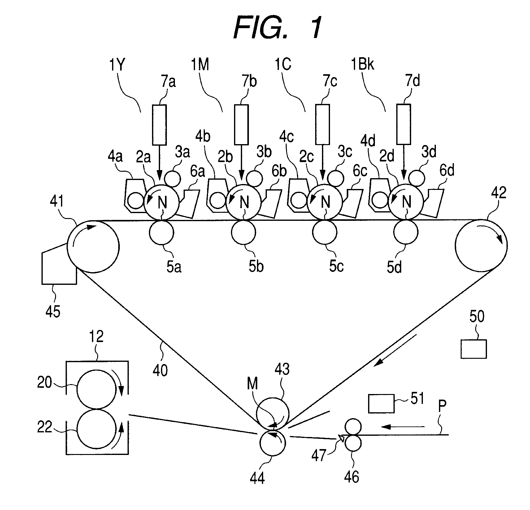
[0078]FIG. 1 schematically illustrates a configuration of a color image forming apparatus according to a first embodiment of the present invention. The image forming apparatus according to this exemplary embodiment is a tandem type electro-photographic full-color printer.

[0079]The image forming apparatus includes four image forming portions, i.e. an image forming portion 1Y for forming an yellow image, a magenta image forming portion 1M, a cyan image forming portion 10, and a black image forming portion 1Bk, and those four image forming portions are arranged in a line with a predetermined distance therebetween.

[0080]The respective image forming portions 1Y, 1M, 1C, and 1Bk include respective photosensitive drums 2a, 2b, 2c, and 2d. Around the respective photosensitive drums 2a, 2b, 2c, and 2d, there are disposed, respectively charging rollers 3a, 3b, 3c, and 3d, developing devices 4a, 4b, 4c, and 4d, transfer rollers 5a, 5b, 5c, and 5d, and drum cleaning devices 6a, 6b, 6c, and 6d. ...

second exemplary embodiment

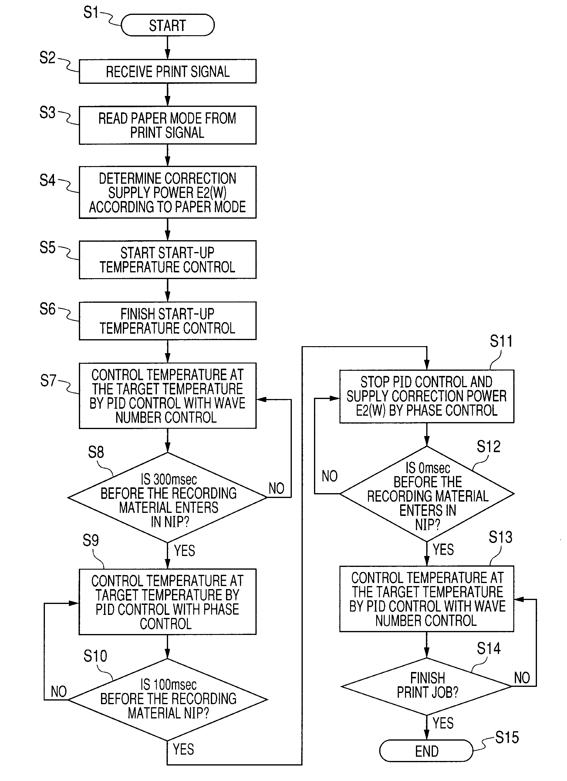
[0183]In the first exemplary embodiment, wave number control is mainly used for controlling the power supply ratio when the power is supplied. In the exemplary embodiment, control combining wave number control and phase control is used. In this case, the power supply ratio in a predetermined cycle is controlled by always including a waveform for supplying power 100% or supplying no power (0% power supply) with respect to one half wave within a predetermined cycle as in the case of the wave number control, and including a waveform for controlling a power supply angle with respect to one half wave within the same cycle, to perform phase control. This control is defined as “hybrid control”.

[0184]More specifically, the hybrid control is basically wave number control with several waves of one half wave or more set as one unit, but phase control is performed with respect to some half waves thereof.

[0185]In this hybrid control, a control cycle includes a waveform for performing phase contr...

third exemplary embodiment

[0205]FIG. 17 schematically illustrates a configuration of a color laser beam printer 200 of a tandem type.

[0206]The color laser beam printer 200 is a printer of a tandem type which includes an image forming portion for each of black (Bk), yellow (Y), magenta (M), and cyan (C) colors. The image forming portions for Y, M, C, and BK respectively include photosensitive drums 1018a, 1018b, 1018c, 1018d, primary chargers 1016a, 1016b, 1016c, 1016d for uniformly charging the photosensitive drums 1018a, 1018b, 1018c, 1018d, respectively, scanner units 1011a, 1011b, 1011c, 1011d for forming a latent image on the respective photosensitive drums 1018a, 1018b, 1018c, 1018d by applying laser beams 1013a, 1013b, 1013c, 1013d respectively, thereto, and developing devices 1014a, 1014b, 1014c, 1014d (developing rollers 1017a, 1017b, 1017c, 1017d) for respectively developing the latent images to be visible. The color laser beam printer 200 further includes primary transfer rollers 1019a, 1019b, 1019...


PUM


Abstract

The image forming apparatus includes a fixing portion, a temperature detection element, and a power control portion. The power control portion is capable of setting a first power supply control mode for supplying power according to the detected temperature for each one control cycle, a second power supply control mode for supplying power according to the detected temperature for each one control cycle and a third power supply control mode for supplying predetermined power, and switches, immediately before a leading edge of the recording material enters the fixing portion, a state of supplying the power in the first power supply control mode to a state of supplying the power in the second power supply control mode, and then switches the state of supplying the power in the second power supply control mode to a state of supplying the power in the third power supply control mode.

Description

BACKGROUND OF THE INVENTION[0001]1. Field of the Invention[0002]The present invention relates to an image forming apparatus which includes a fixing portion for heating an unfixed toner by heat (heat-fixing), formed on a recording material thereon.[0003]2. Description of the Related Art[0004]As heating devices for a recording material, there are conventionally known various methods and configurations such as a heat-roller method, a hot-plate method, a heat-chamber method, and a film-heating method. Those heating devices all include heating elements (heat members). In order to maintain a temperature of the device at a predetermined temperature (predetermined image fixing temperature), the temperature is controlled by controlling power supply to the heating element.[0005]Among such various conventional heating devices, the heating device of the film-heating type is highly effective and practical.[0006]The heating device of the film-heating type includes a thin heat-resistive film, a dr...

Claims


Application Information

Patent Timeline
Patent Type & Authority Patents(United States)
IPC IPC(8): G03G15/20
CPCG03G15/2039G03G15/205G03G2215/2035
Inventor FUKUZAWA, DAIZOIMAIZUMI, TOORUYOSHIOKA, MAHITOSATO, NORIAKIKURATA, MUNEHITOKASUGA, KUNIAKIIKEDA, YOSHIMICHIKUMADA, HIROMITSUKOYAMA, SATORUKITAMURA, TOSHIFUMIMORI, ATSUNOBU
Owner CANON KK
Why Eureka
Try Eureka