Locking mechanism for a wind turbine

a technology of locking mechanism and wind turbine, which is applied in the direction of mechanical equipment, machines/engines, electric generator control, etc., can solve the problems that the stopping of the rotor in a defined and local determined desired position cannot be achieved, and achieve the enhancement of the performance of the locking mechanism, the reduction of the actuation force of the deceleration device, and the control of the gearing performance

Inactive Publication Date: 2012-12-18
AE ROTOR HLDG BV
View PDF11 Cites 16 Cited by
  • Summary
  • Abstract
  • Description
  • Claims
  • Application Information

AI Technical Summary

Benefits of technology

[0010]According to one embodiment of the invention one deceleration device is designed as friction deceleration device and sensor means are provided in an electronic brake for detecting the status, which means among others the actuation force, the actuation distance, the temperature and / or the actuation current. In particular the drive train can comprise a gearing with a fast output shaft and a braking disk, whereas the fast output shaft can be engaged by a deceleration device. Thus the required braking moment and therefore also the actuation force of the deceleration device is reduced significantly.
[0011]In order to enhance the performance of the locking mechanism further sensor means for detecting the position and / or the rotational speed of the fast output shaft or the braking disk are provided. Thus, strains and vibrations of the power train caused by torsion can be included in the estimation of the deceleration process. Furthermore, as an additional effect, the performance of the gearing can be controlled.

Problems solved by technology

Here the essential problem is that a stopping of the rotor in a defined and locally determined DESIRED position can hardly be achieved by the teaching of the invention and the features disclosed in said document.

Method used


Image

  • Locking mechanism for a wind turbine
  • Locking mechanism for a wind turbine
  • Locking mechanism for a wind turbine

Examples


Embodiment Construction

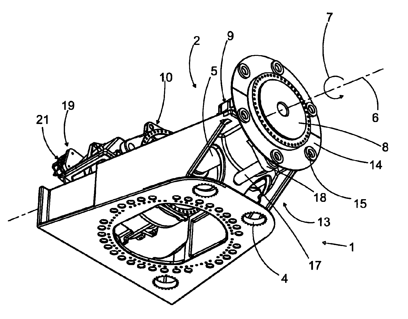
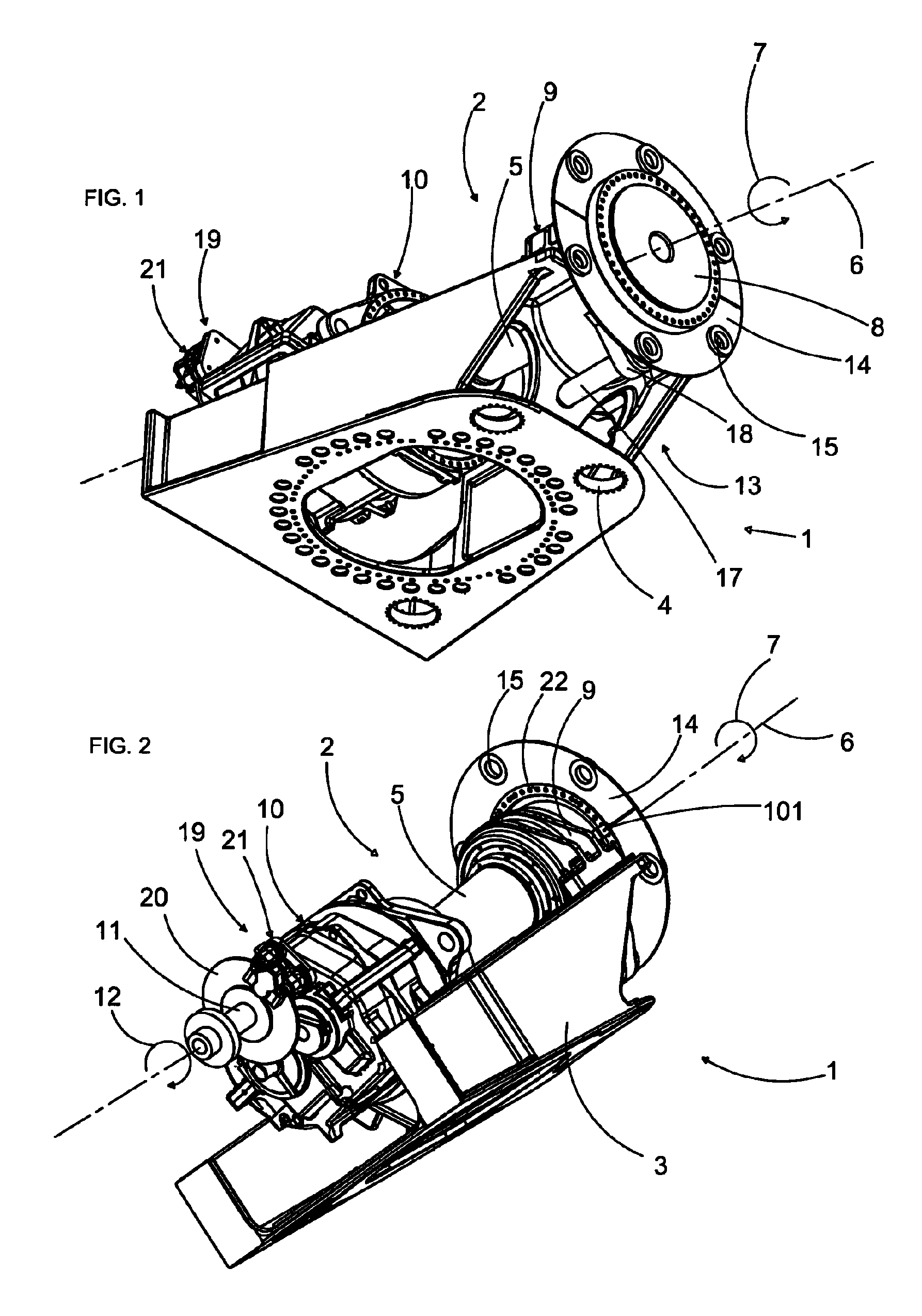
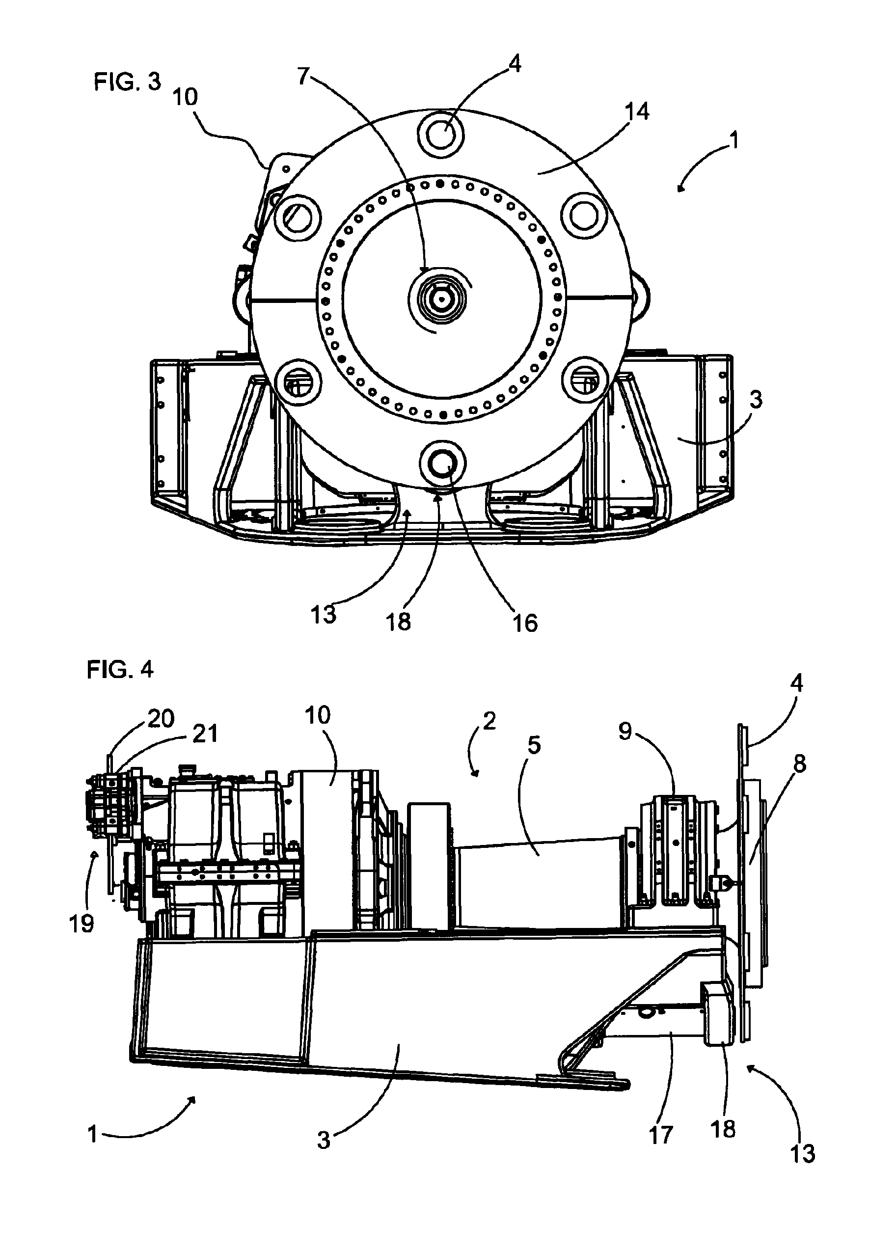
[0028]FIGS. 1 to 4 show different views of one embodiment of the invention. The locking mechanism 1 functions between a drive train 2 and a machine support 3 of the wind turbine which is not completely shown in these drawings. A machine house comprises the machine support 3 and is rotatably mounted on the tower which is not shown in the drawings via an azimuth bearing which is not shown in the drawings. Openings 4 in the machine support 3 are adapted to receive azimuth drives which in co-operation with a rotatably fixed tooth rim of the azimuth bearing represent the yaw control of the machine house.

[0029]In the figures the essential elements of the drive train 2 are shown, whereas a rotor shaft 5 is rotatably mounted about a rotational axis 6 on the machine support 3 via a rotor bearing 9 and via a gearing 10. In the following the rotational axis 6 of the rotor of the wind turbine will be used as a reference system in terms of geometrical specifications. The gearing 10 is used to tr...


PUM


Abstract

A locking mechanism for a wind turbine decelerates and/or locks a rotor or a rotor shaft of the wind turbine. For maintenance work, the rotor or the rotor shaft is lockable to a machine support of the wind turbine in a form-fit manner by utilizing the locking mechanism. A rotational position of the rotor shaft is automatically detected in a DESIRED position. Moreover, the locking mechanism is configured to be automatically engaged when the DESIRED position has been reached. The locking mechanism additionally has at least one deceleration device for affecting the drive train and/or allowing the rotational speed of the rotor and the rotor shaft to be reduced.

Description

[0001]This application is a 371 application of PCT / EP2008 / 004664 filed Jun. 11, 2008, which claims priority to the European application 07090122.8 filed Jun. 18, 2007 and German Application 102007058746.7 filed Dec. 5, 2007.BACKGROUND OF THE INVENTION[0002](1) Field of the Invention[0003]The invention relates to a locking mechanism for a wind turbine, in which a rotor shaft of a drive train is rotatably mounted on a machine support of the wind turbine while the rotor shaft can be connected to a rotor. In order to be able to do maintenance work on the wind turbine, the locking mechanism comprises locking means, especially with a movable locking bolt, which makes it possible to establish a rotationally fixed positive connection between the rotor or the rotor shaft and the machine support. In order do so, a rotational position of the rotor shaft can automatically be detected in a DESIRED position, and, furthermore, the locking means can be automatically engaged when said DESIRED positi...

Claims


Application Information

Patent Timeline
Patent Type & Authority Patents(United States)
IPC IPC(8): F03D9/00H02P9/04
CPCF03D7/0248F03D11/04F05B2260/902F05B2270/32F05B2270/327Y02E10/721Y02E10/723Y02E10/728F03D13/20Y02E10/72F05B2260/31
Inventor PECHLIVANOGLOU, GEORGIOSWAGNER, JURGEN
Owner AE ROTOR HLDG BV
Why Eureka
Try Eureka