ECU arrangement structure for a vehicle

a technology for arranging structures and vehicles, applied in vehicle components, propulsion units, propulsion parts, etc., can solve the problems of increasing the length of the wiring lines, increasing the number of man-hours for assembly, increasing the weight of the vehicle, etc., and reducing the weight of the duct cover. , the effect of raising the support rigidity of the ecu and improving assembly eas

Active Publication Date: 2012-12-25
HONDA MOTOR CO LTD
View PDF13 Cites 6 Cited by
  • Summary
  • Abstract
  • Description
  • Claims
  • Application Information

AI Technical Summary

Benefits of technology

[0007]It is an object of the present invention to solve the subject of the prior art described above and provide an ECU arrangement structure for a vehicle wherein wiring lines connected to an ECU can be reduced in length to prevent a thermal influence upon the ECU and the cooling effect of the ECU can be raised.

Problems solved by technology

Since a large number of wiring lines for inputting output signals of various sensors attached to the engine are connected to the ECU, as the distance between the ECU and the engine increases, the length of the wiring lines increases and the vehicle weight, the number of man-hours for assembly and so forth increase.
Therefore, it is difficult to apply the technique disclosed in Patent Document as it is to the MUV described above to dispose the ECU in the inside of the air cleaner box.
Therefore, the ECU becomes likely to be hit by external air, and consequently, the cooling effect of the ECU can be raised.

Method used


Image

  • ECU arrangement structure for a vehicle
  • ECU arrangement structure for a vehicle
  • ECU arrangement structure for a vehicle

Examples


Embodiment Construction

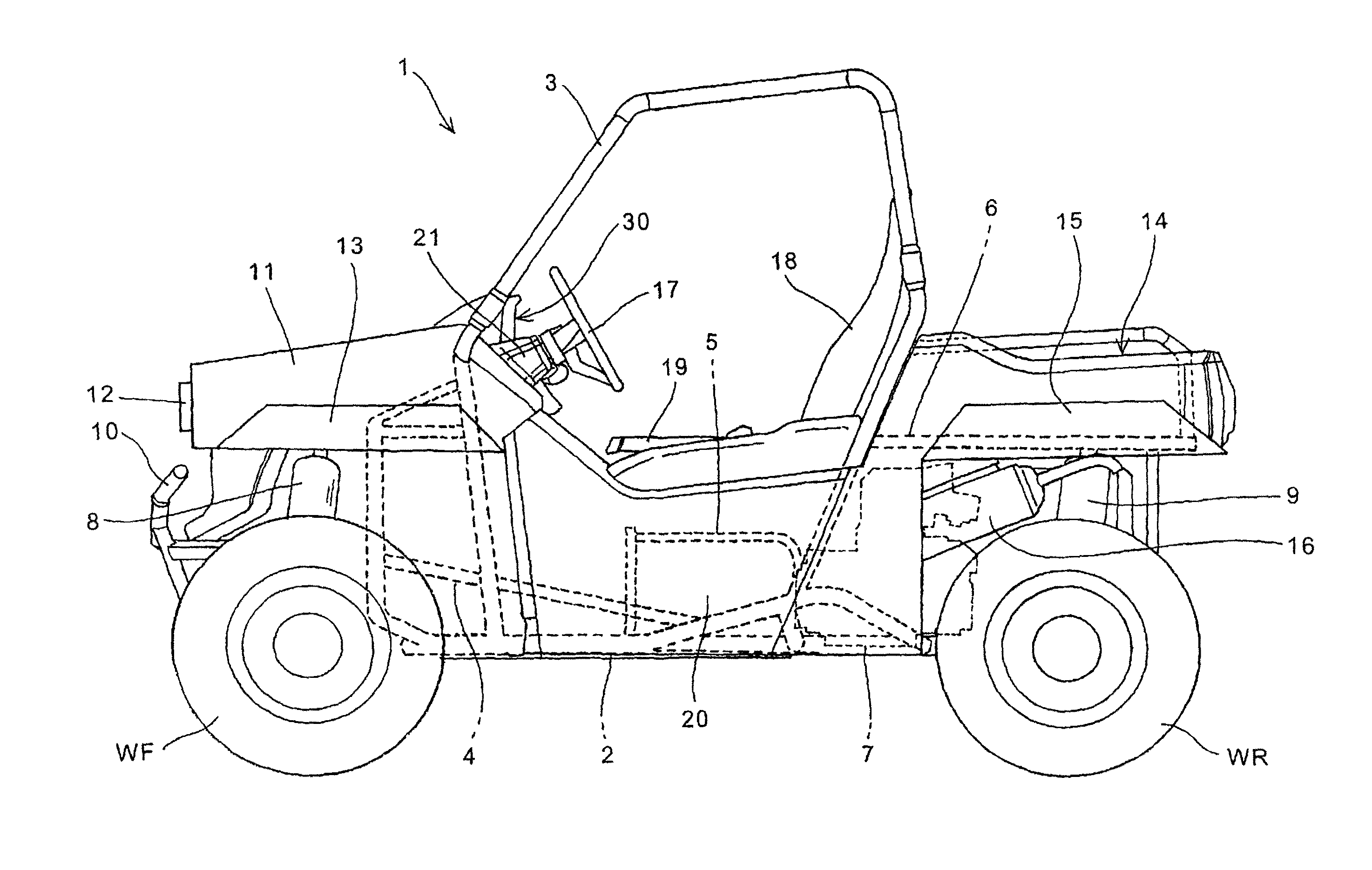
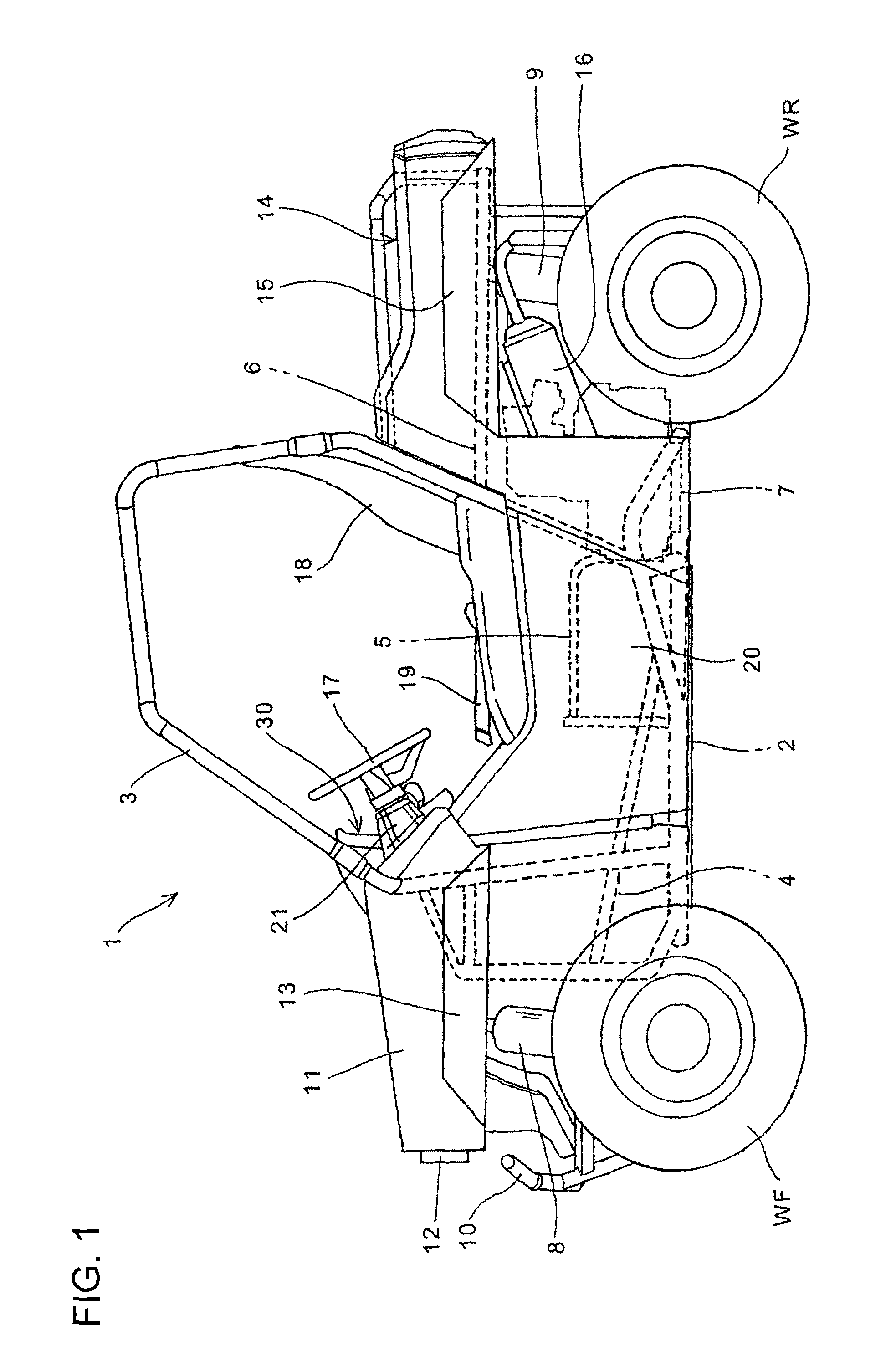
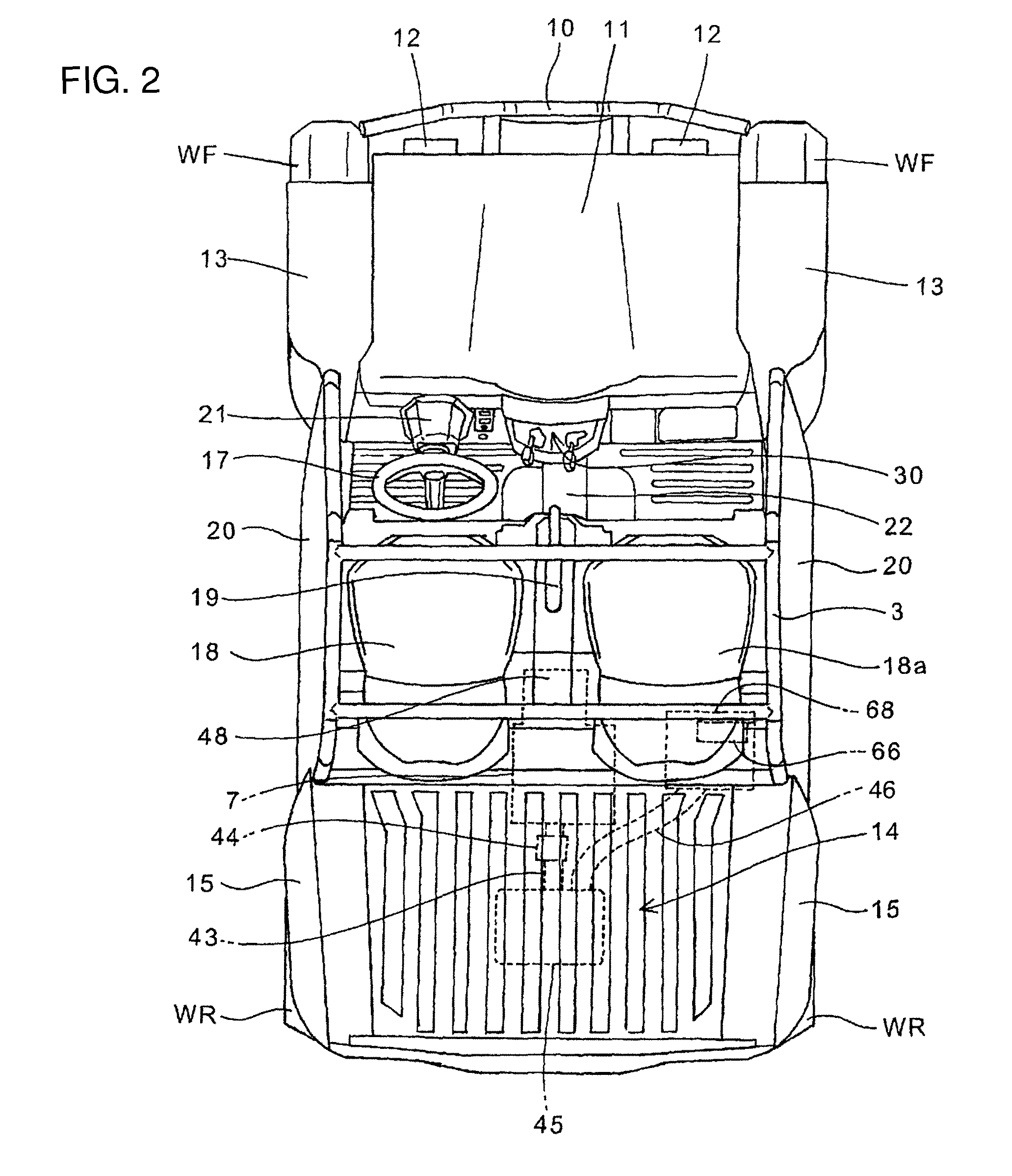
[0045]In the following, a preferred embodiment of the present invention is described in detail with reference to the drawings. FIG. 1 is a side elevational view of a four-wheel vehicle 1 to which an arrangement structure for a vehicle switch according to an embodiment of the present invention is applied. Meanwhile, FIG. 2 is a top plan view of the four-wheel vehicle 1. The four-wheel vehicle 1 in this example is a two-person multi-utility four-wheel vehicle (MUV: multi-utility vehicle) having a cabin which is not screened from the outside. In the following, the four-wheel vehicle is referred to as MUV 1.

[0046]A vehicle body frame 2 of the MUV 1 can be formed by combination of a plurality of steel pipes (frame pipes) and so forth. An engine 7 having an automatic change gear provided integrally thereon is attached to the vehicle body rear side of the vehicle body frame 2. A pair of left and right front wheels WF and a pair of left and right rear wheels WR are supported on the vehicle ...


PUM


Abstract

An engine controller structure for a vehicle, can include a duct cover having a box-like portion on a vehicle body front side thereof. The box-like portion can include an opening formed therein, and can be configured to have an intake duct of an engine connected thereto. The duct cover can be configured to be positioned sidewardly of an engine. An engine control unit can be disposed on the inside of the duct cover. The opening, configured to be connected to the intake duct, can be configured such that the intake duct is connected to an air cleaner box attached to a vehicle body rear side of the engine. The intake duct can shaped so as to be extended to a vehicle body front side from the air cleaner box.

Description

BACKGROUND[0001]1. Field[0002]This invention relates to an ECU arrangement structure for a vehicle, and particularly to an ECU arrangement structure for a vehicle suitable for use with a three-wheel or four-wheel vehicle having a cabin which is not screened from the outside.[0003]2. Description of the Related Art[0004]An ECU (Engine Control Unit) as a controlling apparatus for a vehicle is conventionally known. Since a large number of wiring lines for inputting output signals of various sensors attached to the engine are connected to the ECU, as the distance between the ECU and the engine increases, the length of the wiring lines increases and the vehicle weight, the number of man-hours for assembly and so forth increase. Therefore, in order to suppress the length of the wiring lines, it is a possible idea to dispose the ECU in the proximity of the engine. However, it is necessary to take it into consideration to prevent the ECU, which is a precision apparatus, from being influenced...

Claims


Application Information

Patent Timeline
Patent Type & Authority Patents(United States)
IPC IPC(8): B60K13/02
CPCB60K13/02B60Y2200/114
Inventor SHIRATORI, KENICHIYASHIRO, TOMOHIKOYAMAMOTO, SHOTSURUTA, YUICHIRO
Owner HONDA MOTOR CO LTD
Why Eureka
Try Eureka