
Method and apparatus for generating pseudo random sequence in broadband wireless communication system

a wireless communication system and pseudo-random sequence technology, applied in the field of wireless communication systems, can solve the problems of hardware complexity, hardware complexity increase, and limit to using pseudo-random sequences as scrambling codes requiring different random sequences having good cross-correlations, so as to reduce or maintain the maximum cross-correlation value, maximize the size, and maximize the effect of siz

Active Publication Date: 2013-01-01
PANTECH CORP +2
View PDF1 Cites 4 Cited by
  • Summary
  • Abstract
  • Description
  • Claims
  • Application Information

AI Technical Summary

Benefits of technology

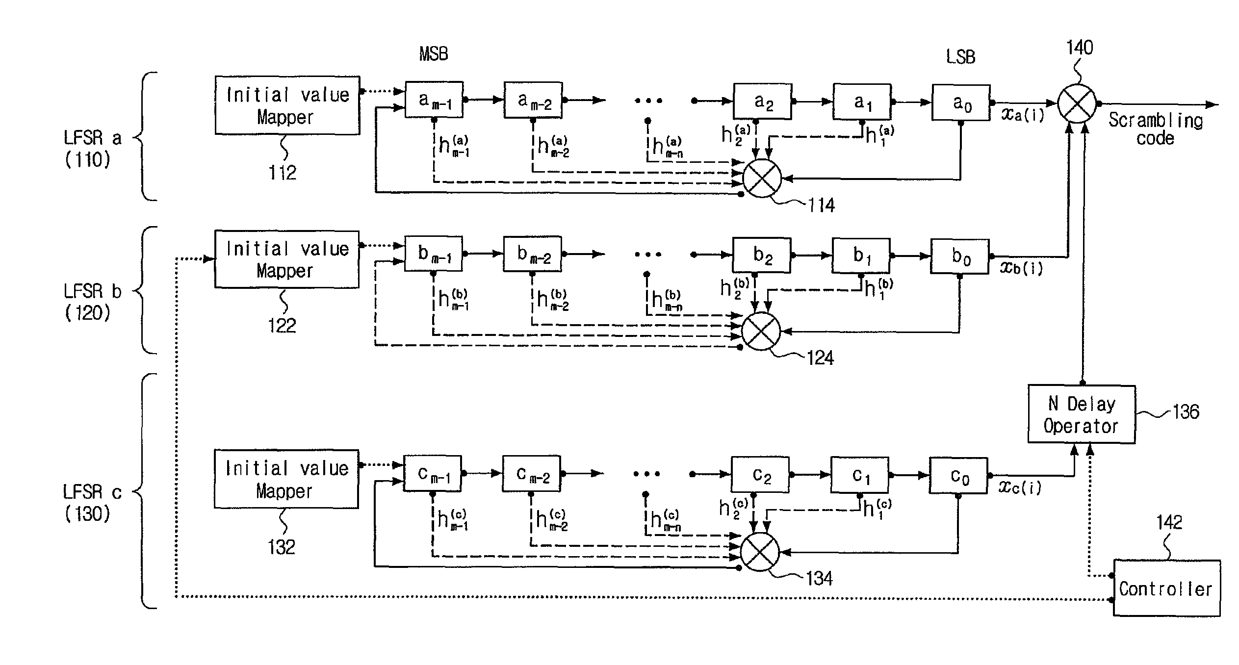
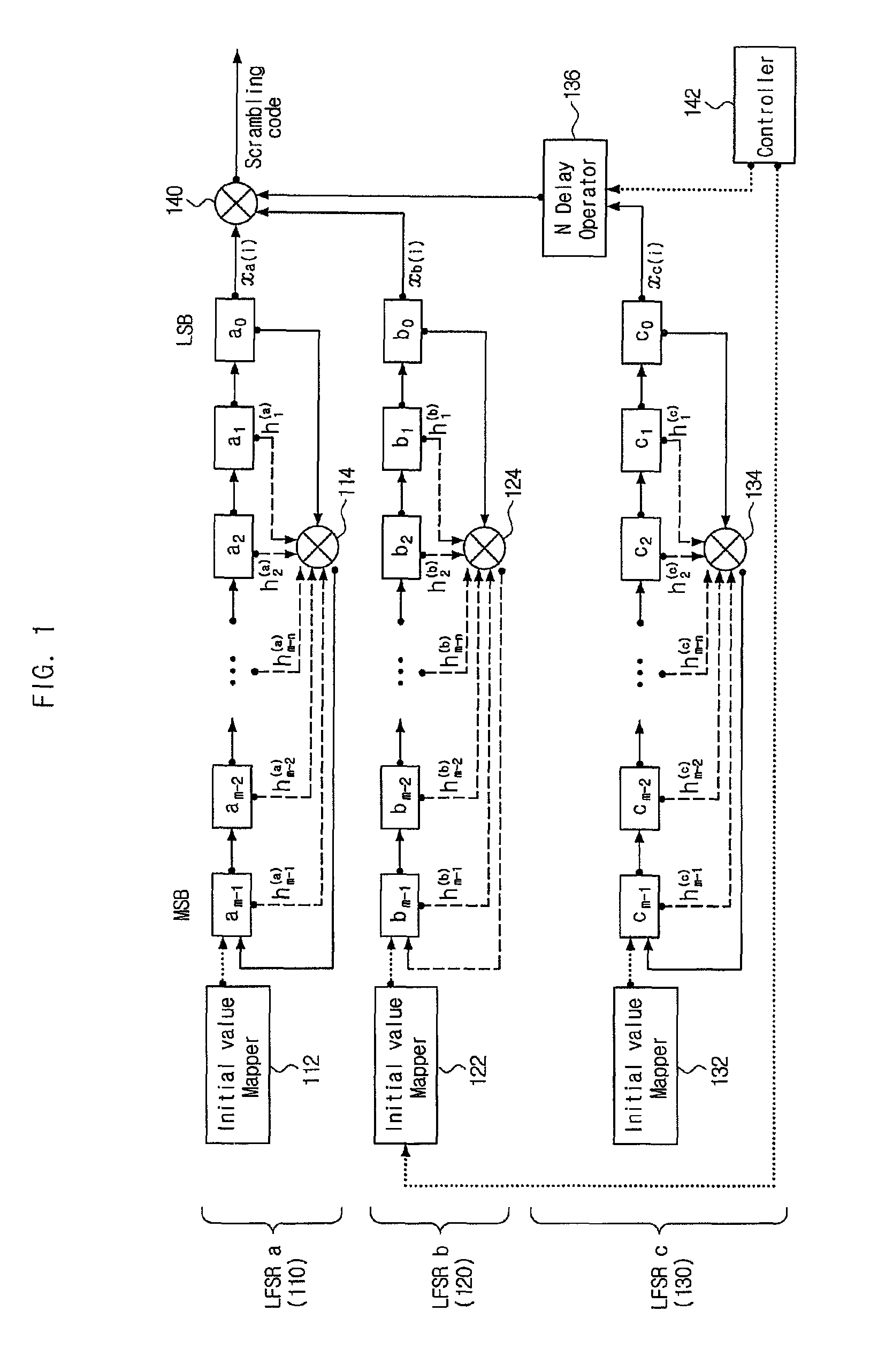
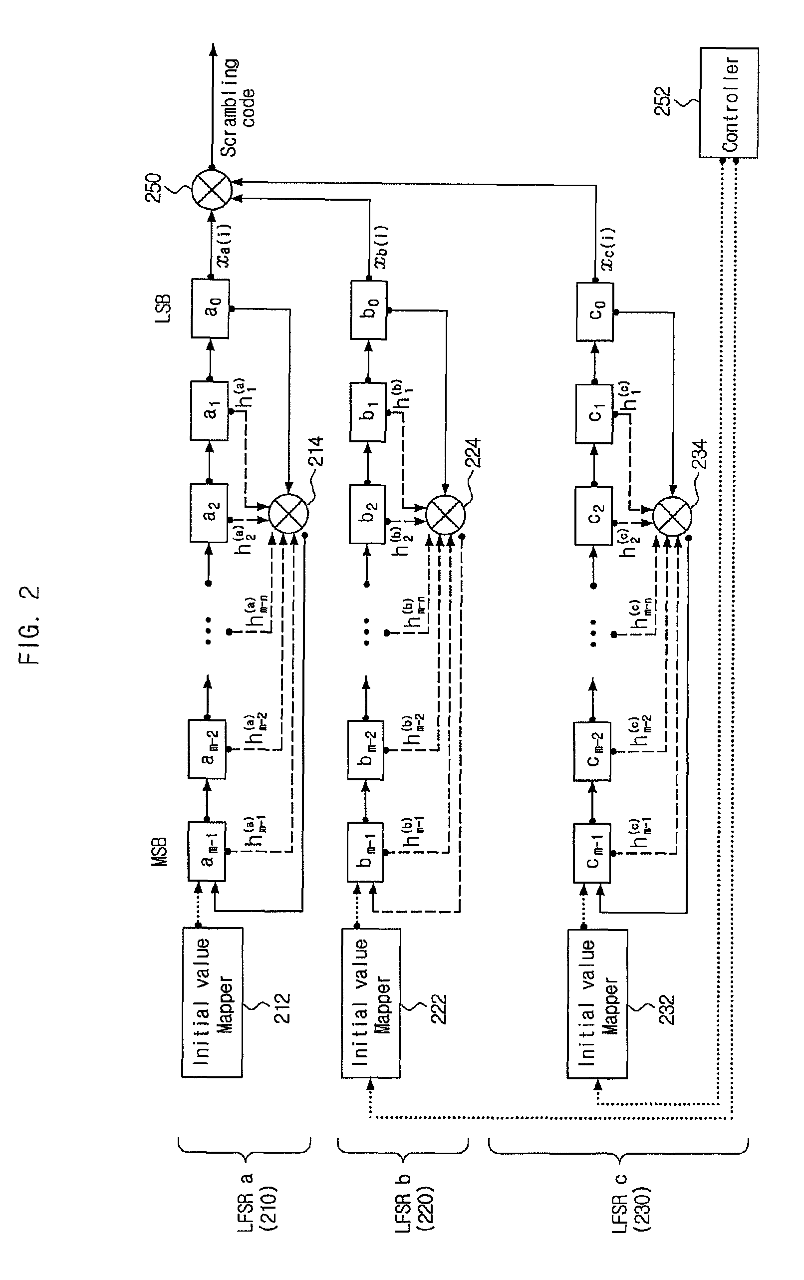
The present invention provides a method and apparatus for generating pseudo random sequence in a broadband wireless communication system to maximize the size of the sequence while reducing or maintaining a maximum cross-correlation value. This is achieved by using three or more linear feedback shift registers (LFSRs) that are individually operated and connected in parallel. This method and apparatus can be employed while maintaining hardware complexity and an operation speed and can be used in various applications, such as communication systems, data encryption, and information security.

Problems solved by technology

However, since the size of only a single m-sequence is 1, there is a limit to using the pseudo-random sequence as scrambling code requiring different random sequences having good cross-correlations (the maximum cross-correlation value is low and the number of kinds of cross-correlations is small).
However, in the method of identifying mobile station-specific and cell-specific system information of 40 to 50 bits or more by using the Gold sequence in the case of m=40 or m=50 or more as the proposed scrambling code, there is a problem in that hardware complexity increases due to blocks (block or box) in a number of LFSRs connected in series.
However, in the case of m=33, in consideration of hardware (HW) based on the 32-bit architecture, there still is a problem in terms of hardware complexity.

Method used


Image

  • Method and apparatus for generating pseudo random sequence in broadband wireless communication system
  • Method and apparatus for generating pseudo random sequence in broadband wireless communication system
  • Method and apparatus for generating pseudo random sequence in broadband wireless communication system

Examples


Embodiment Construction

[0029]The invention is described more fully hereinafter with reference to the accompanying drawings, in which exemplary embodiments of the invention are shown. This invention may, however, be embodied in many different forms and should not be construed as limited to the embodiments set forth herein. Rather, these exemplary embodiments are provided so that this disclosure is thorough, and will fully convey the scope of the invention to those skilled in the art. In the drawings, the size and relative sizes of layers and regions may be exaggerated for clarity. Like reference numerals in the drawings denote like elements.

[0030]The terminology used herein is for the purpose of describing particular embodiments only and is not intended to be limiting of this disclosure. As used herein, the singular forms “a”, “an” and “the” are intended to include the plural forms as well, unless the context clearly indicates otherwise. Furthermore, the use of the terms a, an, etc. does not denote a limit...


PUM


Abstract

Provided are a method and an apparatus for generating pseudo random sequence to generate pseudo random sequences which have larger sizes and are different from each other in a wireless communication system; a method for generating pseudo random sequence in a wireless communication system, comprising generating a first output sequence, generating a second output sequence, and generating a third output sequence; and an apparatus to generate pseudo random sequence in a wireless communication system, comprising a first linear feedback shift register (LFSR), a second LSFR, and a third LFSR, a first initial value mapper, a second initial value mapper, a third initial value mapper, and an N delay operator.

Description

CROSS-REFERENCE TO RELATED APPLICATION[0001]This application claims priority from and the benefit of Korean Patent Application No. 10-2008-0121495, filed on Dec. 2, 2008, which is hereby incorporated by reference for all purposes as if fully set forth herein.BACKGROUND OF THE INVENTION[0002]1. Field of the Invention[0003]This disclosure relates to a wireless communication system, and more particularly, to a method of generating pseudo random sequence in a broadband wireless communication system and an apparatus for generating pseudo random sequence using the method.[0004]2. Discussion of the Background[0005]Scrambling code is used for identifying mobile station (user equipment or UE)-specific and cell (base station)-specific identification information in a wireless communication system. Generally, scrambling code identifies a base station in a downlink and identifies a mobile station in an uplink. This type of scrambling code randomizes or decreases the interference in a mobile stat...

Claims


Application Information

Patent Timeline
Patent Type & Authority Patents(United States)
IPC IPC(8): H04J13/10
CPCH04L9/0662G06F7/584H04L2209/80H04L2209/34H04J13/10H04L27/32
Inventor YOON, SUNG JUNSUH, SUNG JINJUNG, MYUNG CHEUL
Owner PANTECH CORP
Learn More