
Bandwidth allocation method and passive optical network system

a technology of optical network and allocation method, applied in data switching networks, instruments, frequency-division multiplexes, etc., can solve the problem of inability to control the convergence of the allocated bandwidth on the target bandwidth, the inability to specify and the inability to adjust the upper limit of the transmission requirement. problem, to achieve the effect of minimizing the mismatch between the transmission requirement and the transmission permission amoun

Active Publication Date: 2013-01-01
NIPPON TELEGRAPH & TELEPHONE CORP
View PDF8 Cites 7 Cited by
  • Summary
  • Abstract
  • Description
  • Claims
  • Application Information

AI Technical Summary

Benefits of technology

This patent is about a method for allocating bandwidth in a PON network. The method aims to minimize the difference between the amount of bandwidth requested and the amount of bandwidth allowed. It does this by updating a requirement threshold based on the amount of bandwidth needed for a given time period. This allows the network to quickly reach the target bandwidth. The method also allows for control over the speed at which the network reaches the target bandwidth by adjusting a parameter used to compute the requirement threshold. In summary, this patent provides a way to efficiently allocate bandwidth in a PON network to ensure that requests are met while minimizing bandwidth waste.

Problems solved by technology

However, in the conventional method, there are problems that the upper limit of the transmission requirement is not suitable to the quick convergence of the allocated bandwidth on the target bandwidth, and the convergence of the allocated bandwidth on the target bandwidth cannot be controlled.
Therefore, because the upper limit of the transmission requirement is fixed to a value that is not suitable to the control of the allocated bandwidth, not only the allocated bandwidth cannot converge quickly on the target bandwidth, but also the way of the convergence cannot be controlled.
However, there is disclosed no specific procedure of adjusting the upper limit of the transmission requirement.

Method used


Image

  • Bandwidth allocation method and passive optical network system
  • Bandwidth allocation method and passive optical network system
  • Bandwidth allocation method and passive optical network system

Examples


first embodiment

[0050](First Embodiment)

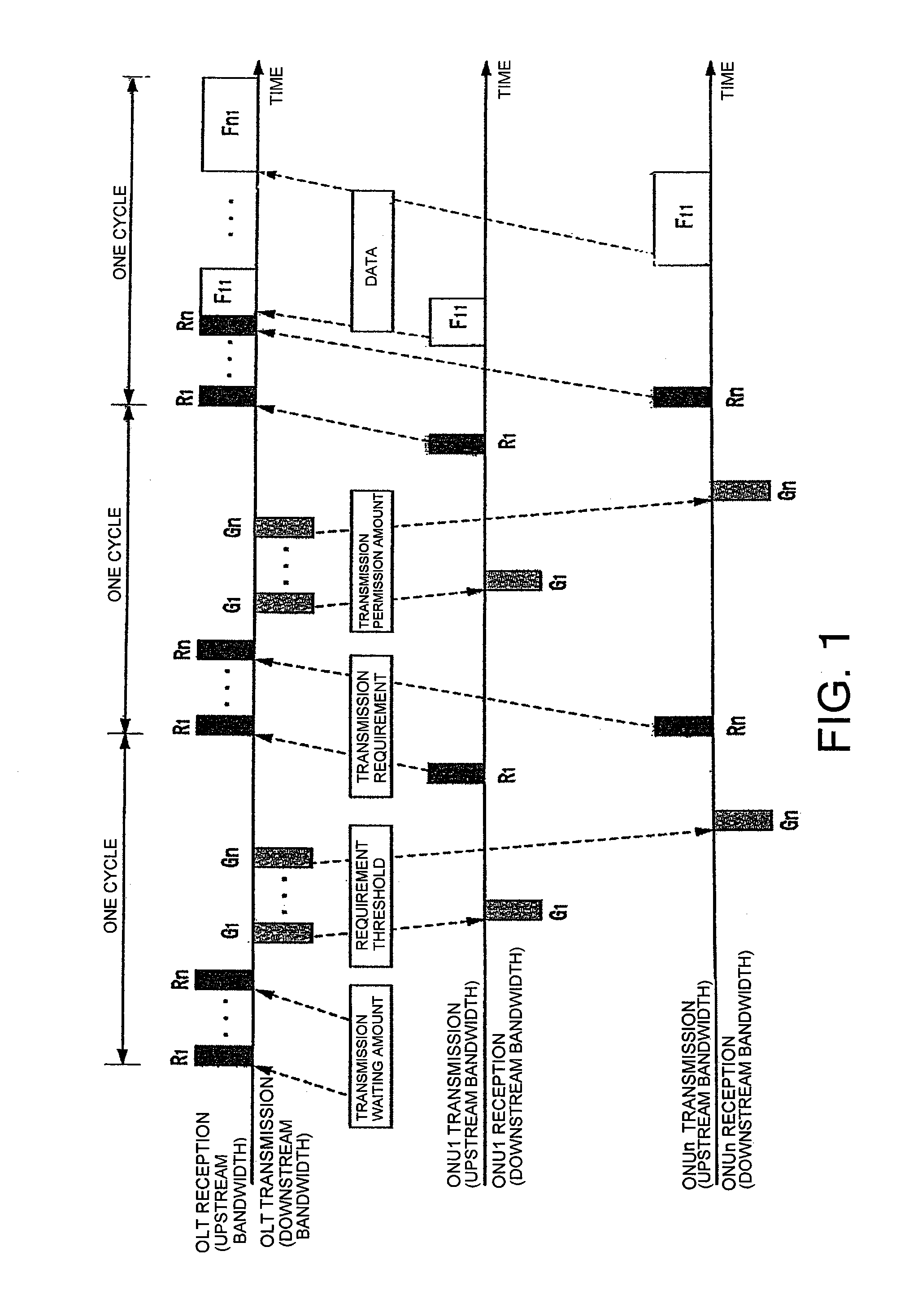
[0051]A method in which an OLT calculates a requirement threshold based on a time average allocated bandwidth obtained from allocated bandwidths of past predetermined cycles of ONU will be described below. For a constant data transmission bit rate, the following amount, bandwidth, and the like may be processed by a data amount or a time. An i-th ONU is expressed by ONUi, and hereinafter a suffix i is added to a parameter of the ONUi. A difference ei between the time average allocated bandwidth of the ONUi and a target bandwidth obtained from a communication state of each ONU is calculated. A PID (Proportional Integral Derivative) computation amount xi is calculated from the following equation:

[0052][Equation⁢⁢1]xi=Pi⁡(ei+Ii⁢∫ei⁢ⅆt+Di⁢ⅆeiⅆt)(1)

where Pi, Ii, and Di are predetermined parameters. The OLT can control the way of the convergence of the allocated bandwidth on the target bandwidth by adjusting values of Pi, and Di (for example, an optimum value is obt...

second embodiment

[0082](Second Embodiment)

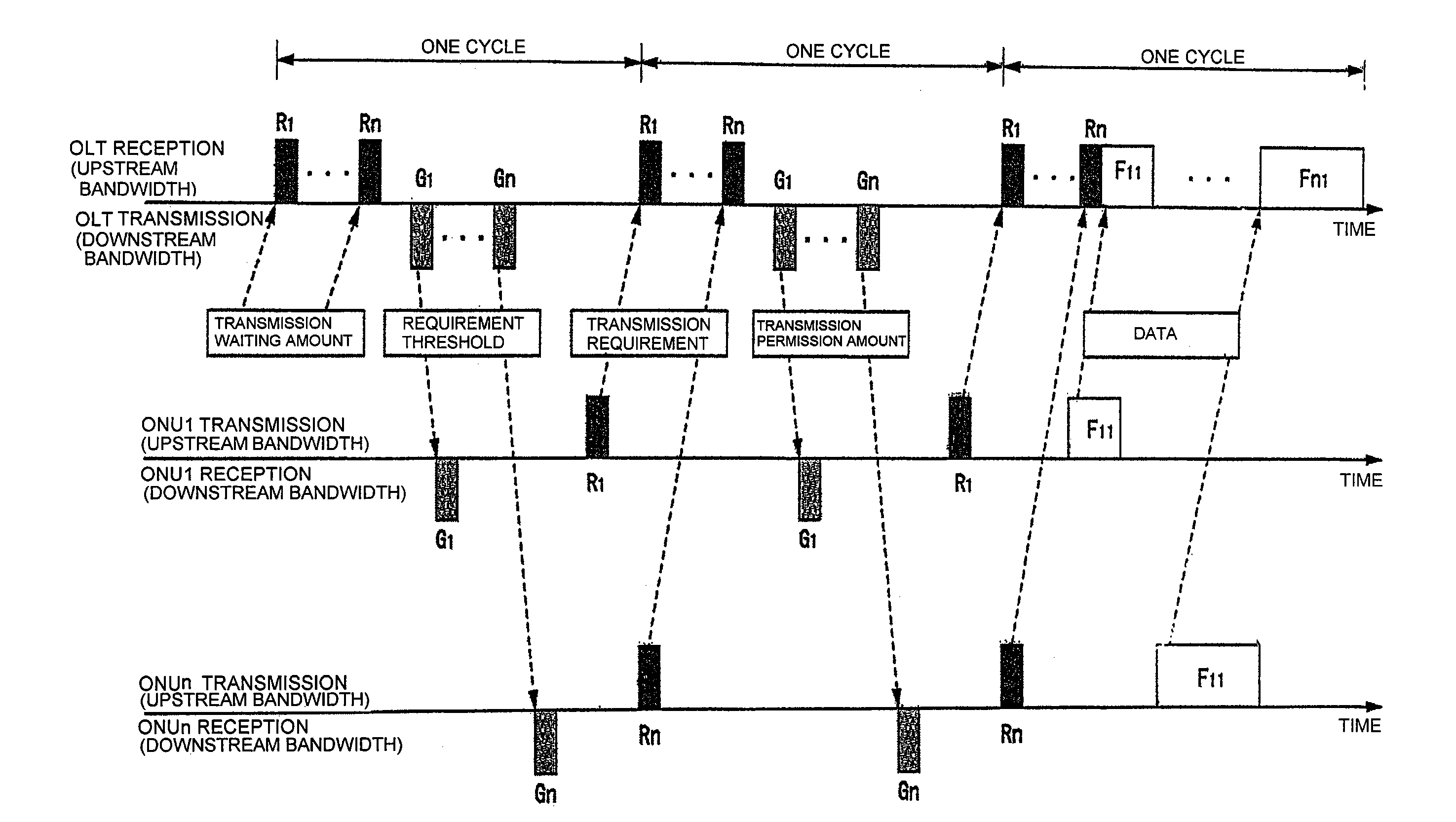
[0083]FIG. 5 is a sequence diagram illustrating an example of a bandwidth allocation method which is performed by a passive optical network system according to a second embodiment of the disclosure. The second embodiment includes a first step, a second step, and a third step in order, and is characterized in that the ONU calculates the requirement threshold zi based on the time average allocated bandwidth obtained from the allocated bandwidths of the past predetermined cycles. The point which is different from that of the first embodiment will specifically be described below.

[0084]First, each ONUi calculates and stores each time average allocated bandwidth. Each of the ONU1 to ONUn, describes a transmission waiting amount ci in the report frame and notifies the OLT of the transmission waiting amount ci in the timing of which the OLT notifies. The OLT calculates a target bandwidth fi based on the transmission waiting amount ci of each of the ONU1 to ONUn. The...


PUM


Abstract

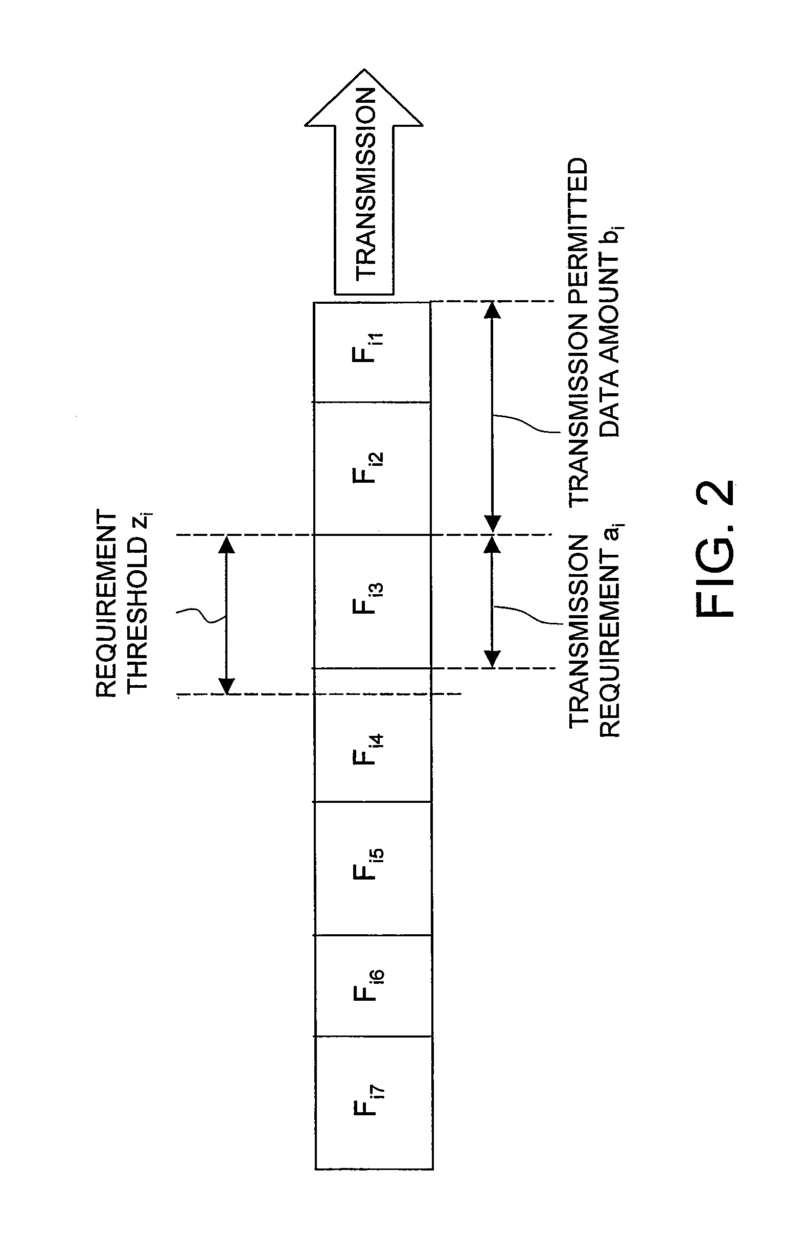
An optical line terminal calculates a requirement threshold for each optical subscriber unit based on a difference between the time average allocated bandwidth of each optical subscriber unit and the target bandwidth, and notifies a corresponding optical subscriber unit of the calculated requirement threshold. The corresponding optical subscriber unit then notifies, based on the data amount accumulated in a buffer, the optical line terminal of a data amount, as a transmission requirement, up to a data separation that is less or equal to the notified requirement threshold and in which a maximum transmission amount can be transmitted. The optical line terminal then notifies the corresponding optical subscriber unit of a transmission permission amount in which the data equal to the transmission requirement of which the optical line terminal is notified can be transmitted. The corresponding optical subscriber unit then transmits the data amount corresponding to the transmission permission amount.

Description

BACKGROUND[0001]1. Field of the Disclosure[0002]The present disclosure relates to a bandwidth allocation method for dynamically allocating an upstream communication time (bandwidth) in a passive optical network and a passive optical network system in which the bandwidth allocation method is adopted.[0003]2. Discussion of the Background Art[0004]Recently users of FTTH (Fiber To The Home) services are increasing with development of the Internet. A PON (Passive Optical Network) including an OLT (Optical Line Terminal) placed in a central office of a communication carrier and an ONU (Optical Network Unit) placed in a user's home is one of modes of FTTH.[0005]The PON is an optical network in which the OLT and the plural ONUs are connected through an optical transmission line such as an optical fiber and a passive optical splitter, and the PON is widely used because of its economical superiority.[0006]In an EPON (Ethernet (a registered trademark) PON) in which the OLT and the ONU conduct ...

Claims


Application Information

Patent Timeline
Patent Type & Authority Patents(United States)
IPC IPC(8): H04J14/00H04L47/76H04L12/44
CPCH04L12/5695H04L47/10H04L47/722H04L47/762H04Q11/0067H04L47/263H04Q2011/0064H04L47/70
Inventor MURAYAMA, DAISUKEOOTA, NORIYUKIMIKI, NORIKI
Owner NIPPON TELEGRAPH & TELEPHONE CORP
Learn More