
Dispenser for refrigerator

a technology for refrigerators and dispensers, which is applied in the field of refrigerators, can solve the problems of large and multifunctional refrigerators, enlarging the installation space of refrigerator dispensers, and reducing the storage space of refrigerators, so as to improve the reliability of dispenser operations and reduce the installation space of dispensers

Active Publication Date: 2013-01-08
LG ELECTRONICS INC
View PDF20 Cites 9 Cited by
  • Summary
  • Abstract
  • Description
  • Claims
  • Application Information

AI Technical Summary

Benefits of technology

The present invention is a dispenser for refrigerators that has the following benefits. First, it requires less space for installation because it has a motion conversion unit that activates the switch when the transfer member is rotated. Second, it is designed with simple configurations such as the transfer member and oblique member that prevent undesired operations and enhance the reliability of the dispenser's operational performance.

Problems solved by technology

Currently, the refrigerators have been large and multifunctional according to various demands of users and changes of dietary life thereof.
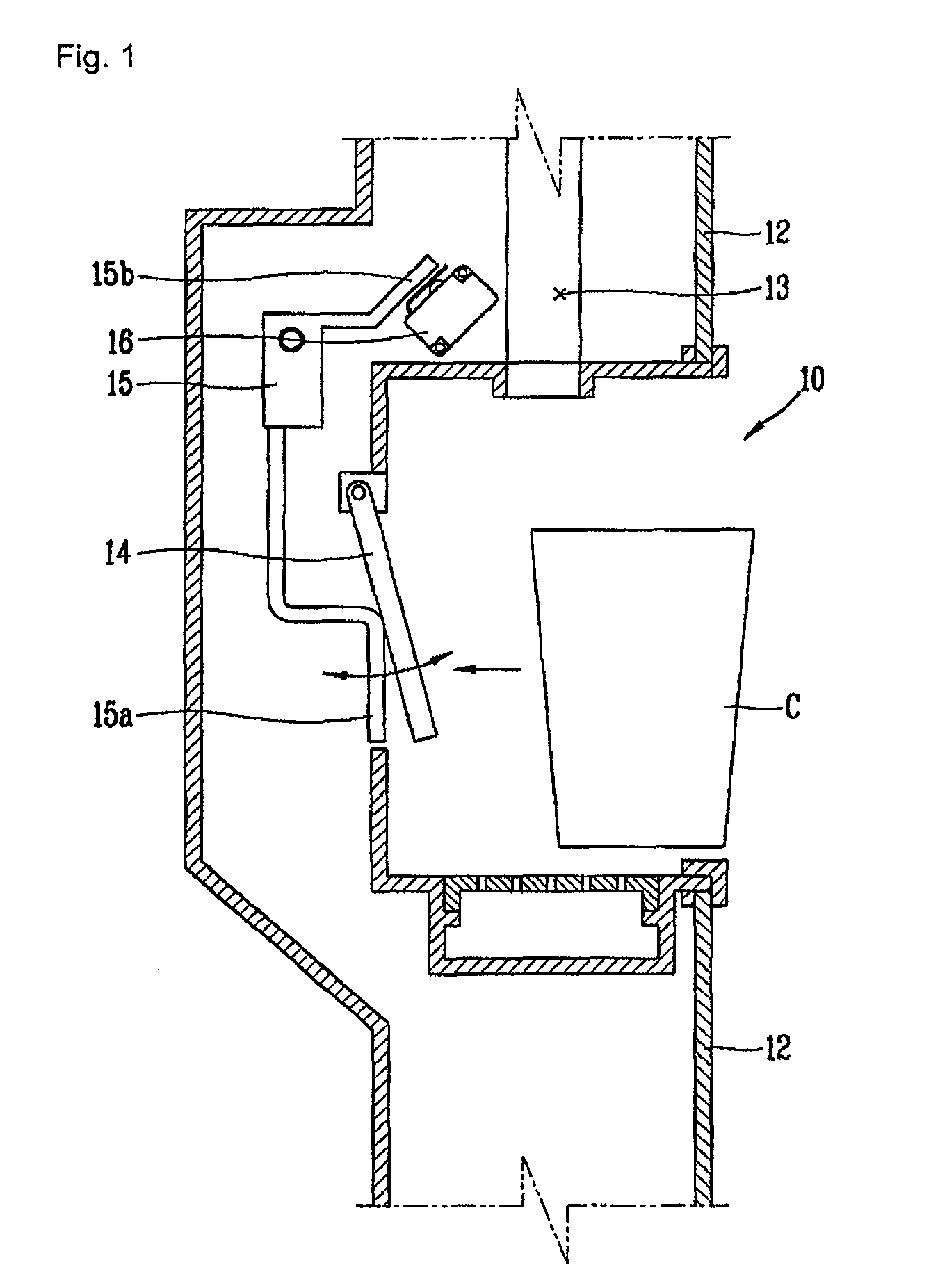
However, in the aforementioned dispenser of the refrigerator in the related art, since the transfer mechanism is rotated with respect to the rear surface of the dispenser housing, a spare space for rotation of the transfer mechanism is required to be formed at the rear surface of the dispenser housing, thereby enlarging an installation space for the dispenser for refrigerator and decreasing a storage space of the refrigerator.

Method used


Image

  • Dispenser for refrigerator
  • Dispenser for refrigerator
  • Dispenser for refrigerator

Examples


first embodiment

[0033]Description will now be given in detail of a dispenser for refrigerator in accordance with the present invention, examples of which are illustrated in the accompanying drawings.

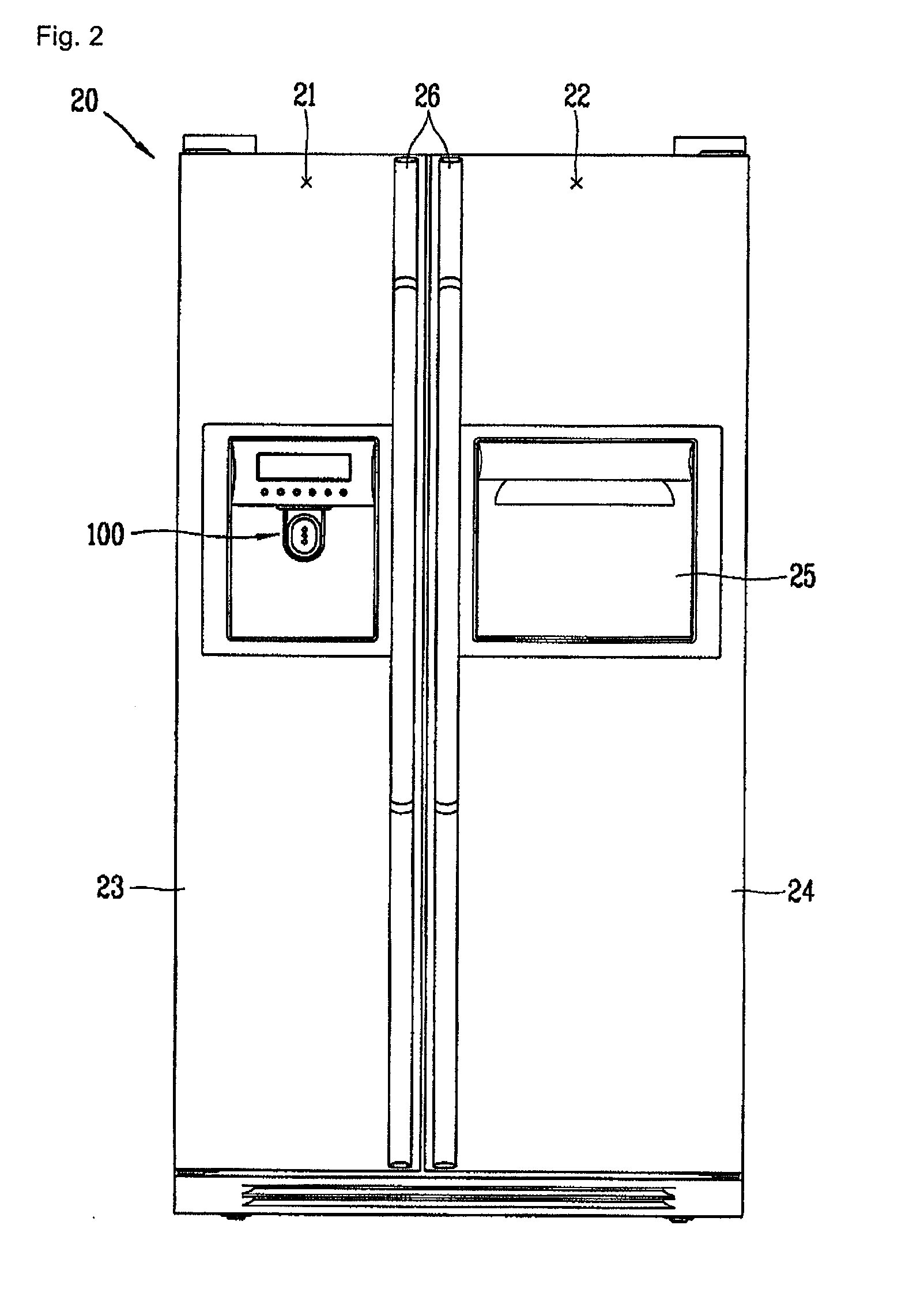
[0034]FIG. 2 is a front view showing an external appearance of a refrigerator to which the dispenser for refrigerator in accordance with the first embodiment of the present invention is applied.

[0035]Referring to FIG. 2, a main body 20 forming the external appearance of the refrigerator is approximately formed in a rectangular parallelepiped shape. A cooling chamber 22 and a freezing chamber 21, storage spaces for storing foods therein respectively in a chilling manner and a freezing manner, are respectively formed in the main body 20. Each front surface of the freezing chamber 21 and the cooling chamber 22 is configured to be open.

[0036]And, refrigerator doors 23, 24 are respectively provided at the opened front surfaces of the freezing chamber 21 and the cooling chamber 22. The refrigerator doors 23, ...

second embodiment

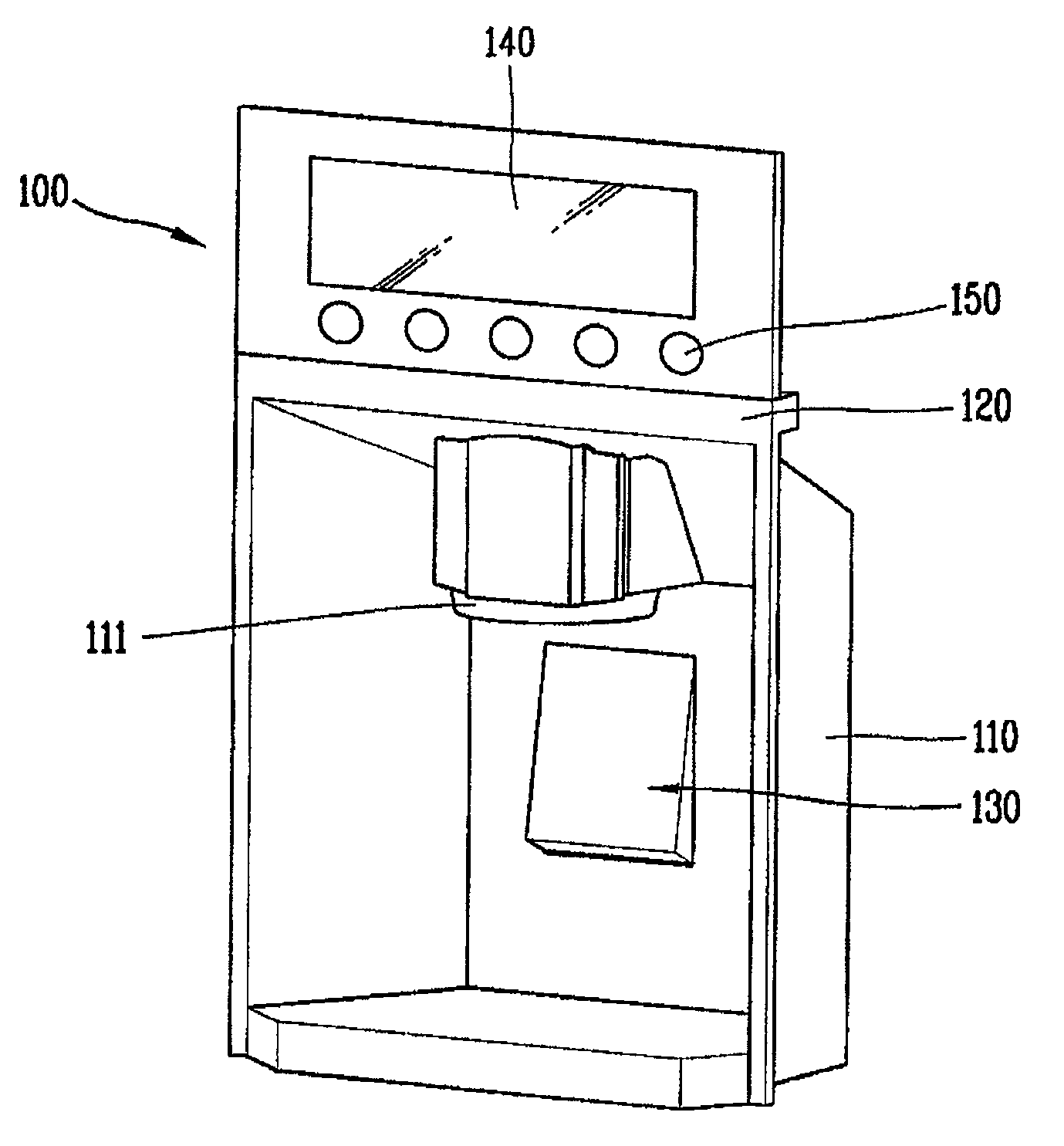
[0067]FIG. 5 shows a rear surface of a dispenser operating apparatus in the dispenser for refrigerator in accordance with the present invention.

[0068]Referring to FIG. 5, in this embodiment, a pushing member 231 included in the dispenser operating apparatus 230 is generally implemented as a planar member in a rectangular shape and is elastically supported at one side of the dispenser housing 210 forming the external appearance of the dispenser. That is, fixed protrusions 211a, 211b, 211c, 211d formed at the dispenser housing and coupling protrusions 231a, 231b, 231c, 231d formed at the rear surface of the pushing member 231 are respectively coupled to each other, and elastic members 232 are respectively interposed between the fixed protrusions 211a, 211b, 211c, 211d and the coupling protrusions 231a, 231b, 231c, 231d.

[0069]Accordingly, the switch 235 can receive a pushing force even when a certain position of the pushing member 231 is pushed, thereby enhancing reliability of operat...


PUM

PropertyMeasurementUnit
pushing forceaaaaaaaaaa
specific angleaaaaaaaaaa
lengthaaaaaaaaaa

Abstract

A dispenser for a refrigerator including a pushing member formed in a planar shape and configured to be movable in a back and forth direction, a switch configured to be operated by a pushing force applied to be parallel with the pushing member, and a motion conversion unit cooperating with the motion of the pushing member to enable the switch to be pushed, wherein the motion conversion unit includes an oblique member configured to be protruded obliquely from one side of a rear surface of the pushing member, and a transfer member coming in contact with the oblique member and the switch and having one side fixed to be rotatable in parallel with the pushing member.

Description

TECHNICAL FIELD[0001]The present invention relates to a refrigerator, and more particularly, to a dispenser for a refrigerator for discharging out water or ice cubes from the dispenser of the refrigerator.BACKGROUND ART[0002]Generally, a refrigerator, an appliance for storing food at a low temperature, stores foods in a freezing manner or a cooling manner depending upon states of foods to be stored.[0003]Currently, the refrigerators have been large and multifunctional according to various demands of users and changes of dietary life thereof. Such refrigerator generally has a dispenser for discharging out purified water or ice cubes without opening a door thereof.[0004]The dispenser is generally formed at the door of the refrigerator and is manipulatable in various manners. An exemplary dispenser in the related art is shown in FIG. 1.[0005]FIG. 1 is a side section view schematically showing a dispenser for refrigerator in the related art.[0006]Referring to FIG. 1, the dispenser for r...

Claims


Application Information

Patent Timeline
Patent Type & Authority Patents(United States)
IPC IPC(8): B67D3/00B67D7/06B67D7/80B65B1/04B65B3/00B65C3/00F25D3/00
CPCF25C5/005F25D23/12F25D23/028F25D2400/361F25D23/126F25C5/22F25D11/00F25D25/00
Inventor CHOI, DAE-JIN
Owner LG ELECTRONICS INC
Learn More