Planetary reduction gear apparatus

a technology of planetary reduction gear and gear shaft, which is applied in the direction of belt/chain/gearing, toothed gearing, belt/chain/gearing, etc., can solve the problems of substantial deterioration of the life span of the planetary reduction gear shaft, and achieve the reduction of material amount, simple structure, and positive reduction of base plate stiffness

Active Publication Date: 2013-01-08
KAWASAKI HEAVY IND LTD
View PDF17 Cites 12 Cited by
  • Summary
  • Abstract
  • Description
  • Claims
  • Application Information

AI Technical Summary

Benefits of technology

[0007]With the aforementioned configuration, bending deformation of each planetary shaft can be successfully restrained due to the lowered stiffness of the part adjacent to the one end of the planetary shaft. Particularly, the stiffness of the part of the base plate adjacent to the one end of the planetary shaft may be lowered relative to the stiffness of the back plate. Thus, unwanted displacement or deformation of the planetary shaft can be effectively suppressed. Therefore, misalignment between the planetary gear supported by each corresponding planetary shaft and the sun gear as well as misalignment between the planetary gear and the ring gear can be securely suppressed, thereby significantly improving the life span of the planetary reduction gear apparatus.
[0014]As described above, according to the planetary reduction gear apparatus of this invention, the occurrence of misalignment can be effectively reduced with a simple structure, as well as the life span thereof can be significantly improved.

Problems solved by technology

Further, with such misalignment, unbalanced contact between the gears and / or bearings will be likely to occur, leading to substantial deterioration of the life span of the planetary reduction gear apparatus.

Method used


Image

  • Planetary reduction gear apparatus
  • Planetary reduction gear apparatus
  • Planetary reduction gear apparatus

Examples


Embodiment Construction

[0025]Hereinafter, preferred embodiments of the present invention will be described, with reference to the drawings.

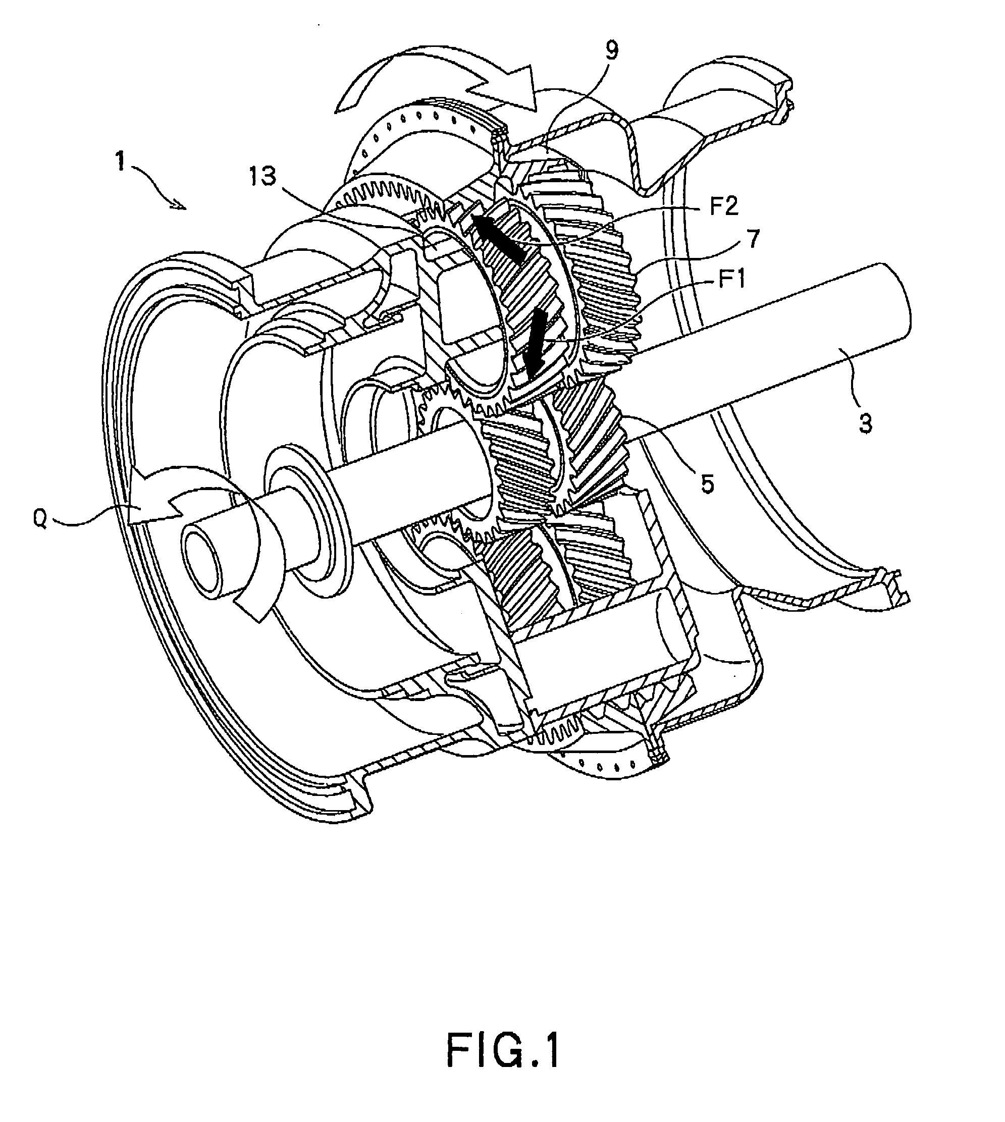
[0026]Referring to FIG. 1 showing the planetary reduction gear apparatus 1 of the first embodiment of the present invention, the planetary reduction gear apparatus 1 is provided in, for example, an airplane or helicopter, while being connected with a gas turbine engine (not shown) via an input shaft 3. In this case, the power outputted from the gas turbine engine will be transmitted via the apparatus to two rotors (not shown), independently, as two kinds of different power. As used herein, one side, in an axial direction, on which the gas turbine engine is located (i.e., a left lower side in FIG. 1), will be referred to as “a front side”, while the other side will be referred to “a back side.”

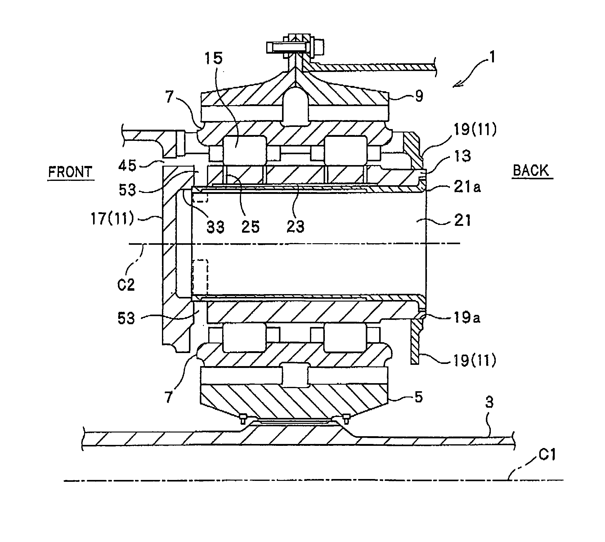
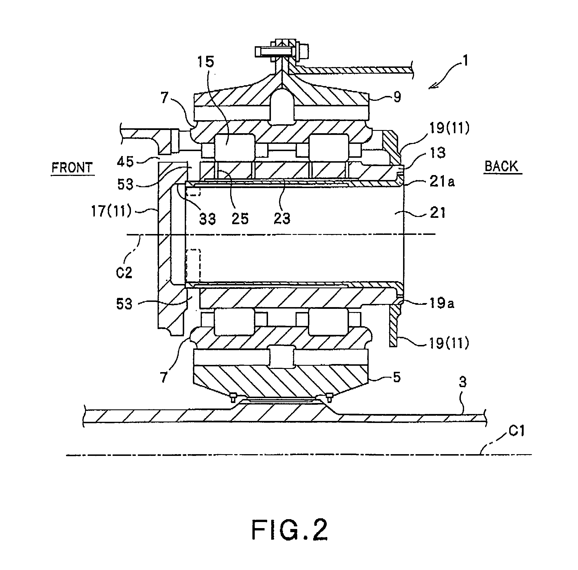
[0027]FIG. 2 is a longitudinal section of the planetary reduction gear apparatus 1 shown in FIG. 1. As shown in FIG. 2, the planetary reduction gear apparatus 1 has a multiple-row...


PUM


Abstract

A planetary reduction gear apparatus has a sun gear having external teeth; planetary gears, each having external teeth and configured to be meshed with the sun gear; planetary shafts, each being a rotation shaft of the planetary gear; a ring gear having internal teeth and configured to be meshed with the planetary gears; and a planetary carrier including an annular base plate and an annular back plate. The planetary carrier supports the planetary shafts between the annular base plate and the annular back plate and determines a relative position between planetary gears. The annular base plate is integrally formed with one end of the planetary shaft to support the one end. The annular back plate supports the other end of the planetary shaft. At least one of the planetary shaft and the planetary carrier has lower stiffness in its part adjacent to the one end of the planetary shaft than stiffness of its part adjacent to the other end thereof.

Description

CROSS REFERENCE TO RELATED APPLICATIONS[0001]This application is based upon the prior Japanese Patent Applications No. 2008-107971 filed on Apr. 17, 2008 and No. 2009-097981 filed on Apr. 14, 2009, the entire contents of which are incorporated herein by reference.TECHNICAL FIELD[0002]The present invention relates to a planetary reduction gear apparatus used in particular for a power transmission mechanism for an aircraft.BACKGROUND ART[0003]Conventionally, the planetary reduction gear apparatus of this type includes a sun gear having external teeth, a plurality of planetary gears, each having external teeth and configured to be meshed with the sun gear, a common planet carrier adapted for supporting a rotation shaft of each planetary gear and configured to determine a relative position between each adjacent planetary gears, and a ring gear having internal teeth and configured to be meshed with the planetary gears. In this gear system, power generated from a power source, such as a g...

Claims


Application Information

Patent Timeline
Patent Type & Authority Patents(United States)
IPC IPC(8): F16H57/08
CPCF16H1/2827F16H57/082F16H1/48F16H1/2836
Inventor MATSUOKA, TETSUYANISHIKAWA, HIROYASUNISHIDA, TOORUAKAHORI, HIROFUMIGOI, TATSUHIKO
Owner KAWASAKI HEAVY IND LTD
Why Eureka
Try Eureka