
Maintaining communication between network nodes that are subjected to a packet attack

a network node and packet attack technology, applied in the field of telecommunication, can solve the problems of reducing the overall availability of the other nodes in the system b, increasing the processing load of the gatekeeper, and reducing the overall availability of the gatekeeper

Active Publication Date: 2013-01-08
AVAYA INC
View PDF7 Cites 0 Cited by
  • Summary
  • Abstract
  • Description
  • Claims
  • Application Information

AI Technical Summary

Benefits of technology

The present invention helps prevent problems caused by packet attacks without the limitations of previous techniques. It does this by periodically sending a message to another device that certain communications with the first device should be suspended. The second device refrains from sending keep-alive messages to the first device for a predetermined interval, and the first device refrains from sending keep-alive messages to the second device for a similar interval. This prevents devices from continuing to communicate under the mistaken belief that each other is unavailable. The invention can also disable the interface through which the packet attack stream enters, conserving processing cycles and reducing the impact of the attack.

Problems solved by technology

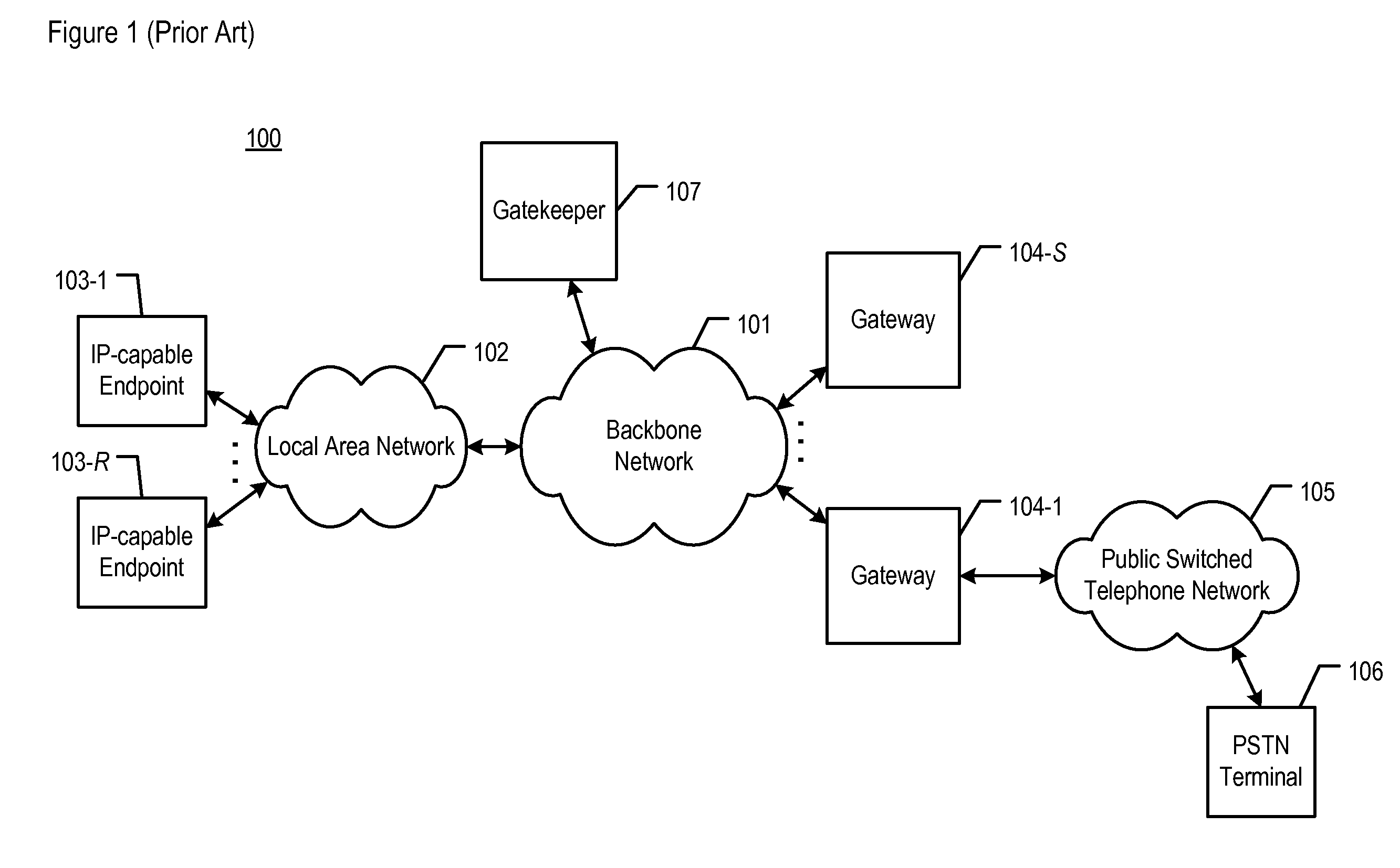
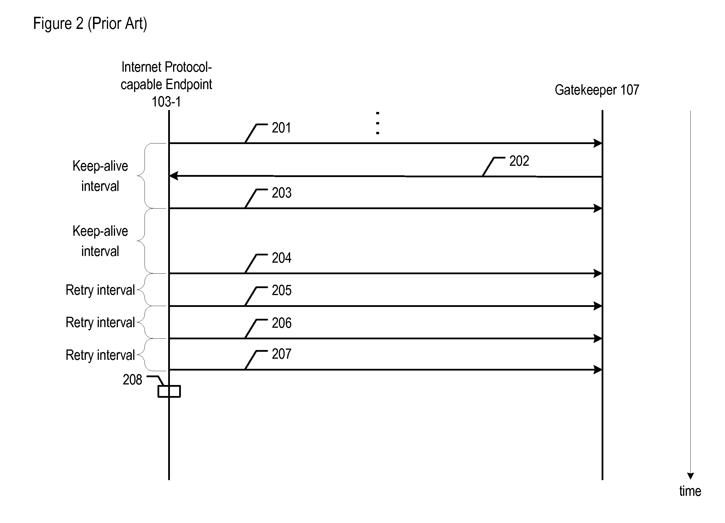
As implied above, the absence of a heartbeat leads to additional message traffic in the network and increases the processing load on gatekeeper 107, which possibly degrades its performance and reduces its overall availability to the other nodes in system 100.
Furthermore, if a large number of endpoints were to reregister concurrently, a flood of registration-related messages would occur, creating an even higher load on gatekeeper 107 and ultimately leading to degraded performance across system 100.

Method used


Image

  • Maintaining communication between network nodes that are subjected to a packet attack
  • Maintaining communication between network nodes that are subjected to a packet attack
  • Maintaining communication between network nodes that are subjected to a packet attack

Examples


Embodiment Construction

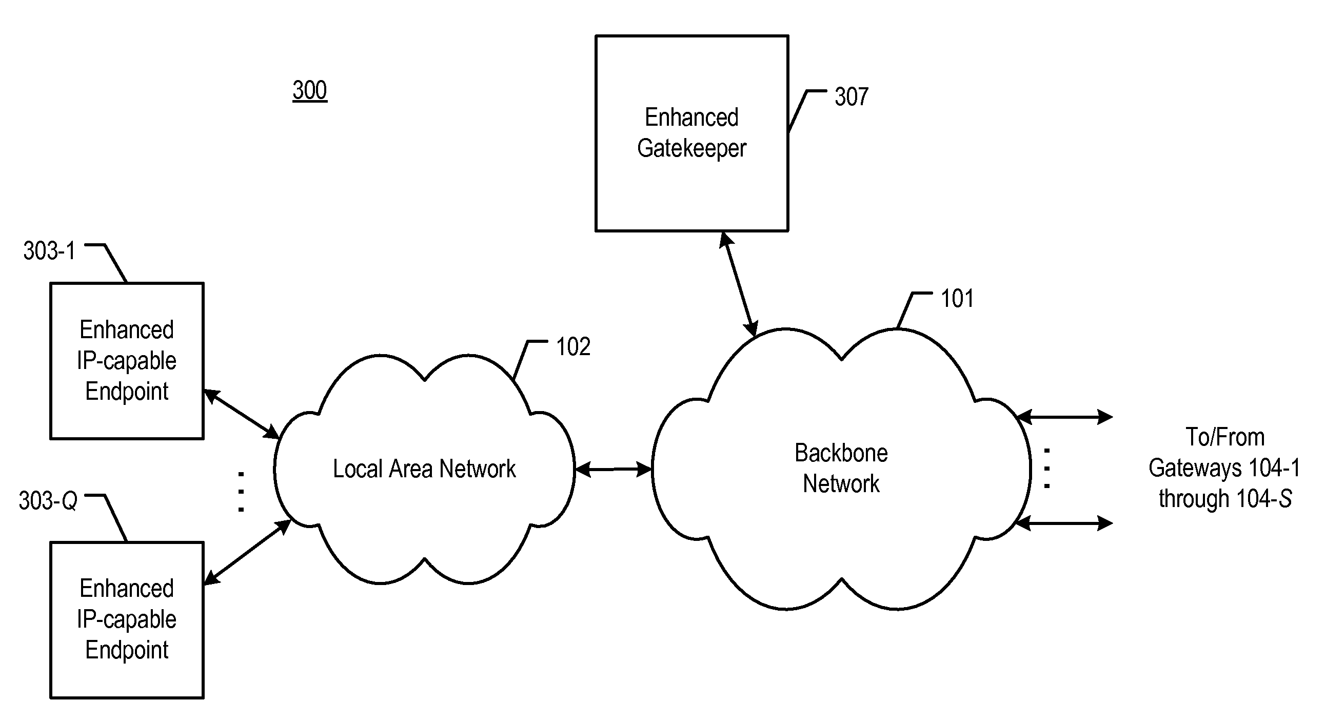
[0032]FIG. 3 depicts a schematic diagram of telecommunications system 300 in accordance with the illustrative embodiment of the present invention. Telecommunications system 300 comprises:[0033]i. backbone packet network 101;[0034]ii. local area network 102;[0035]iii. enhanced Internet Protocol-capable endpoints 303-1 through 303-Q, wherein Q is a positive integer; and[0036]iv. enhanced gatekeeper 307.

All of the elements depicted in FIG. 3 are interconnected as shown. In addition, system 300 comprises gateways 104-1 through 104-S, Public Switched Telephone Network (PSTN) 105, and PSTN telecommunications terminal 106, all of which are described above and with respect to FIG. 1, as are backbone packet network 101 and local area network 102.

[0037]System 300 is similar to system 100 in that it is able to transmit voice conversations between end-user devices. However, as those who are skilled in the art will appreciate, in some alternative embodiments of the present invention, the present...


PUM


Abstract

A method is disclosed that enables mitigating at least some of the problems caused by a packet attack. When a first Internet Protocol (IP)-capable device is subjected to a packet attack, it indicates periodically to a second IP-capable device that certain communications with the first device are to be suspended. The periodic transmitting of the indication is performed at a slower rate than the keep-alive mechanism that is normally used to detect loss of connectivity. When the second device receives the transmitted indication, it refrains from transmitting keep-alive messages to the first device for a predetermined interval. Meanwhile, the first device also refrains from transmitting keep-alive messages to the second device for a similar interval. In transmitting the suspend indication, the illustrative embodiment seeks to prevent pairs of communicating devices that are experiencing packet attacks from continuing their operation under the erroneous assumption that each device is unavailable.

Description

FIELD OF THE INVENTION[0001]The present invention relates to telecommunications in general, and, more particularly, to maintaining communication between two network nodes when one or both nodes are subjected to a packet attack.BACKGROUND OF THE INVENTION[0002]Voice over Internet Protocol (or “VoIP”) features the routing of voice conversations over the Internet or through another type of Internet Protocol-based network. Voice signals from the voice conversations to be routed are digitized and formatted into data packets, which are then transmitted through the network. A telecommunications network that is based on VoIP is able to transmit voice conversations between devices that are able to access the network. FIG. 1 depicts a schematic diagram of telecommunications system 100 in the prior art, which is able to transmit voice conversations between end-user devices such as telephones. Telecommunications system 100 comprises:[0003]i. backbone packet network 101;[0004]ii. local area netw...

Claims


Application Information

Patent Timeline
Patent Type & Authority Patents(United States)
IPC IPC(8): G06F21/00
CPCH04L63/1408H04L63/1458
Inventor ADHIKARI, AKSHAYGARG, SACHINKRISHNAKUMAR, ANJUR SUNDARESANSINGH, NAVJOT
Owner AVAYA INC
Learn More