Detecting operating mode of hybrid vehicles

a hybrid vehicle and operating mode technology, applied in the direction of instruments, structural/machine measurement, traffic control systems, etc., can solve the problems of insufficient incentives, insufficient air pollution in urban areas, and inability to take into account in what operating mode vehicles, etc., to achieve efficient policing of low-emission zones and save processing costs

Active Publication Date: 2015-01-01
FUJITSU LTD
View PDF18 Cites 19 Cited by
  • Summary
  • Abstract
  • Description
  • Claims
  • Application Information

AI Technical Summary

Benefits of technology

[0061]In this way, the present invention enables a pollution management system to be implemented which monitors the operating modes of vehicles such as hybrid vehicles and as such enables efficient policing of low-emission zones in future Smart Cities. Embodiments enable the detection of a widely varying collection of modes and not merely whether a vehicle is being run in a zero-emission mode or not. Additionally, by coupling the operations of thermal and visual cameras, savings in processing are enabled by allowing precise location of the exhaust with respect to the number plates / ground to be inferred, thereby enabling analysis of the thermal image using fewer samples.

Problems solved by technology

Nowadays, the majority of air pollution in urban areas comes directly from road traffic rather than industry.
However, such incentives to date do not take account of in what operating mode vehicles are actually driven.
If pollution management is to adapt to this trend, it will no longer be sufficient to simply match a vehicle to a single pollution category based on the automated recognition of its number plates at the designated check point (usually a point of entry into a pollution-critical area).
Design of a potential solution is complicated by the fact that various hybrids will contribute a widely varying degree of pollutants depending on the mode they are operating in (dropping down to no pollutants at all when they are operating in an electric-only mode, as in the case of HEVs).
Until now, however, there has been no consideration of the various operating modes available to hybrid vehicles, or for providing a pollution management solution which takes such operating modes into account.

Method used


Image

  • Detecting operating mode of hybrid vehicles
  • Detecting operating mode of hybrid vehicles
  • Detecting operating mode of hybrid vehicles

Examples


Embodiment Construction

[0069]Reference will now be made in detail to the embodiments, examples of which are illustrated in the accompanying drawings, wherein like reference numerals refer to the like elements throughout. The embodiments are described below to explain the present invention by referring to the figures.

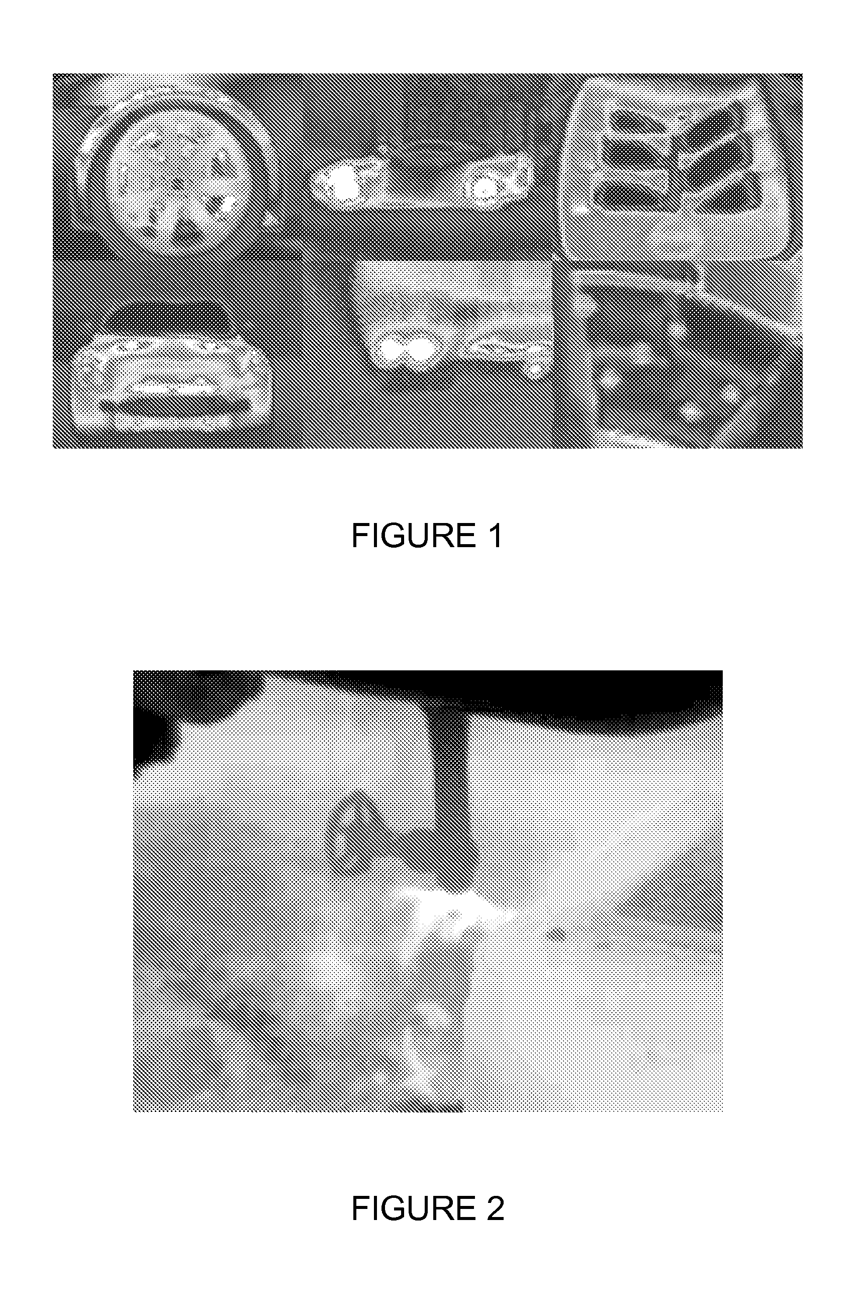
[0070]A hot body (an object at a temperature higher than that of its surroundings) radiates infrared radiation. Thermal imaging allows this radiation to be visualized, and reveals the distribution of temperature over the hot body since the wavelength of infrared radiation varies with temperature.

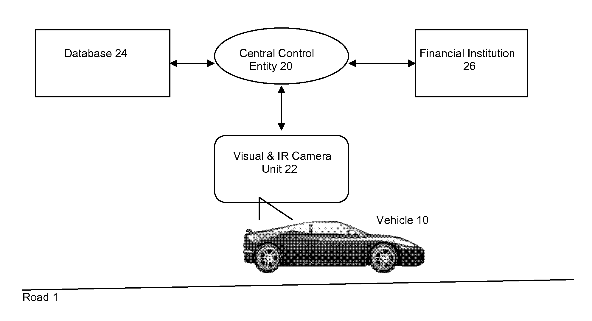
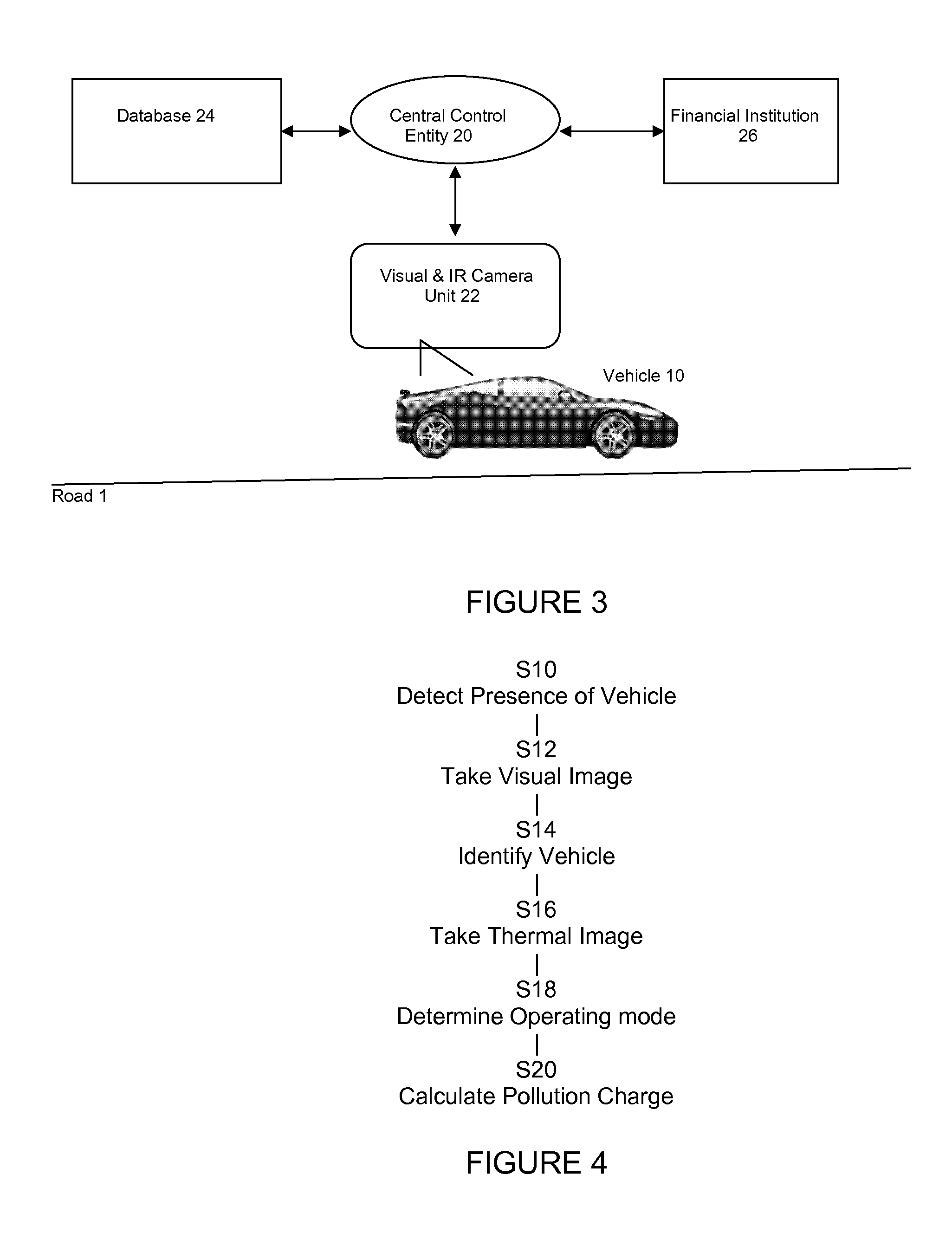
[0071]A principle of the invention is to use thermal imaging for mode recognition of vehicles, by detecting the temperature signature of the exhaust pipe / engine / parts of chassis and to match that signature to a bank of thermal signatures (for exhausts / engines / chassis etc.) for various makes of cars operating in different modes.

[0072]FIG. 1 is a set of thermal images of a car running on an internal comb...


PUM


Abstract

A method for detecting the operating mode of a hybrid vehicle using roadside cameras, said method including the analysis of thermal images of parts of the vehicle and/or exhaust fumes, in combination with associated images of the number plates obtained using visual camera(s) operating in synchronism with said thermal camera and used for vehicle make inference and driver identification. The inferred make of the car is used for aforementioned analysis of thermal images. In a variant, the method is used to verify an operating mode reported by, or obtained from information reported by, the vehicle itself. The method can be used in a pollution management system for calculating financial charges to vehicle drivers in a low-emission zone of a Smart City for example.

Description

CROSS-REFERENCE TO RELATED APPLICATIONS[0001]This application claims the benefit of application Ser. No. 13 / 174,369.2, filed Jun. 28, 2013, the disclosure of which is incorporated herein by reference.BACKGROUND[0002]1. Field[0003]The present invention relates to detecting the current operation mode of vehicles for the purposes of vehicle emission control, including the operating mode of hybrid vehicles such as, but not restricted to, hybrid electric vehicles (HEVs).[0004]2. Description of the Related Art[0005]Conventional motor vehicles such as cars and trucks employ an internal combustion engine (ICE) running on petrol or diesel fuel. By contrast, hybrid vehicles use a mixture of power or fuel sources. A subclass of hybrid vehicles is the hybrid electric vehicle, or HEV. Hybrid vehicles use an electric motor, powered by a battery and / or by a generator, in addition to the ICE. So-called “full” hybrids can operate on fuel by running the internal combustion engine, on stored electrica...

Claims


Application Information

Patent Timeline
Patent Type & Authority Applications(United States)
IPC IPC(8): G07C5/08
CPCG07C5/0808G01N21/3504G01N2021/1793G01N2021/3531G07C5/008G08G1/015G08G1/04G08G1/207
Inventor TESANOVIC, MILOSVADGAMA, SUNIL KESHAVJI
Owner FUJITSU LTD
Why Eureka
Try Eureka