Liquid aspirating tube, liquid dispensing apparatus and liquid dispensing method

a technology of liquid aspiration tube and liquid dispensing method, which is applied in the direction of analytical using chemical indicators, laboratory glassware, instruments, etc., can solve the problem of impaired analysis accuracy

Active Publication Date: 2013-01-15
SYSMEX CORP
View PDF22 Cites 16 Cited by
  • Summary
  • Abstract
  • Description
  • Claims
  • Application Information

AI Technical Summary

Problems solved by technology

When residual liquid in the pipette tip adheres to the tip of the dispensing nozzle, the liquid used in a subsequent analysis may be contaminated even though the pipette tip is replaced, thereby the accuracy of the analysis may be impaired.
When the art disclosed in Japanese Laid-Open patent Publication No. 11-248714 is applied to the dispensing device using this type of pipette tip, problems arises such as (1) the position of the leading end of the descending pipette tip and the position of the pressing plate must be set in proximity in order to apply a horizontal force to the pipette tip by the pressing plate in conjunction with the descent of the pipette tip, because due to the narrow angle of the tapered part of the pipette tip.

Method used


Image

  • Liquid aspirating tube, liquid dispensing apparatus and liquid dispensing method
  • Liquid aspirating tube, liquid dispensing apparatus and liquid dispensing method
  • Liquid aspirating tube, liquid dispensing apparatus and liquid dispensing method

Examples


Embodiment Construction

[0029]The preferred embodiments of the present invention are described hereinafter based on the drawings.

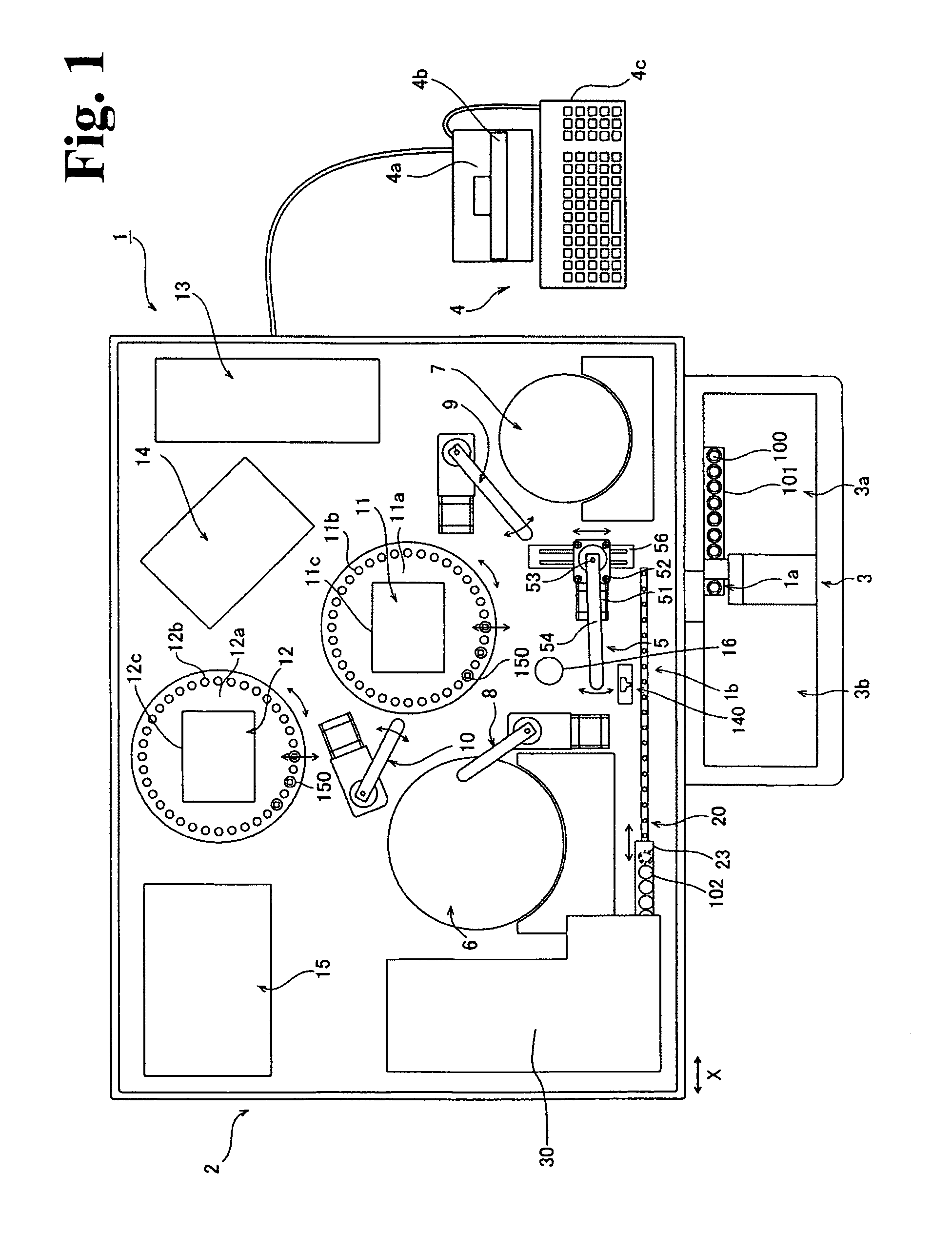
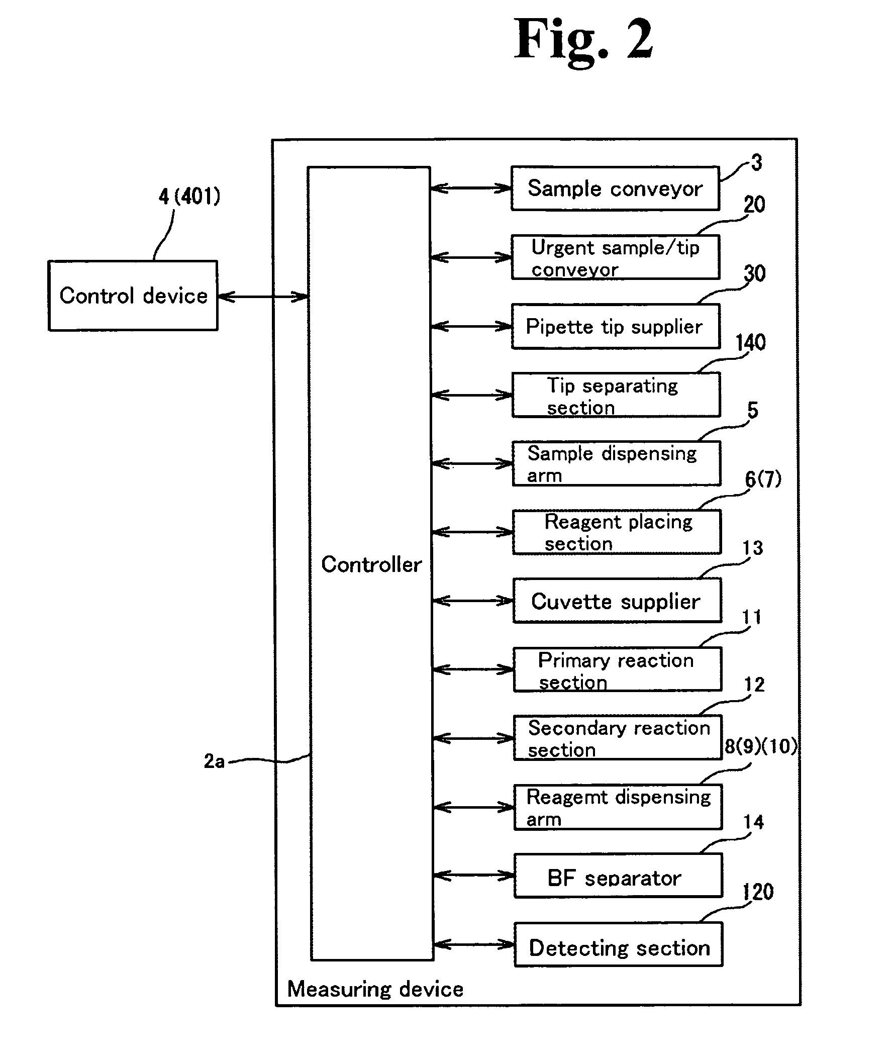
[0030]The overall structure of the immunoanalyzer 1 of an embodiment of the present invention is described below with reference to FIGS. 1 and 2.

[0031]The immunoanalyzer 1 of the present embodiment of the invention performs examinations using samples such as blood for various items such as hepatitis B, hepatitis C, tumor markers, thyroid hormone and the like. The immunoanalyzer 1 removes an R1 reagent, which includes free capture antibodies, by attracting bound reagent, capture reagent, and magnetic particles to a magnet (not shown in the drawings) of the BF (Bound Free) separator 14 (refer to FIGS. 1 and 2) after magnetic particles (R2 reagent) have been bound to capture antibodies (R1 reagent) bonded to the antigen contained in a measurement object sample such as blood or the like. Then, after the antigen with bound magnetic particles has bonded with a labeling antibody (R3 rea...


PUM

PropertyMeasurementUnit
diameteraaaaaaaaaa
angleaaaaaaaaaa
horizontal forceaaaaaaaaaa

Abstract

The present invention is to present a liquid dispensing apparatus which is capable of preventing contamination by previously aspirated liquid, even when residual liquid in a pipette tip separated from the dispensing apparatus is scattered. The liquid dispensing apparatus includes: sample dispensing arm 5 which comprises a dispensing nozzle 54b for aspirating and discharging sample on which a pipette tip 200 is attached; tip separating section 140 for separating the pipette tip 200 from the dispensing nozzle 54b; and nozzle wiping section 16 for cleaning a tip of the dispensing nozzle 54b.

Description

RELATED APPLICATIONS[0001]This application claims priority under 35 U.S.C. §119 to Japanese Patent Application No. 2007-094429 filed Mar. 30, 2007 and Japanese Patent Application No. 2007-094563 filed Mar. 30, 2007, the entire contents of which are hereby incorporated by reference.FIELD OF THE INVENTION[0002]The present invention relates to a liquid aspirating tube, a liquid dispensing apparatus and liquid dispensing method for aspirating liquid such as sample, reagent and the like by using a pipette tip.BACKGROUND[0003]In analyzers which have a dispensing nozzle for aspirating and discharging liquid such a blood sample, reagent and the like, it is important to prevent contamination by a previously aspirated liquid in order to ensure the accuracy of the analysis when another new liquid is aspirated after the previously aspirated liquid was discharged. Therefore, for example, Japanese Laid-Open Patent Publication No. H6-3364 discloses a dispensing device in which a disposable pipette...

Claims


Application Information

Patent Timeline
Patent Type & Authority Patents(United States)
IPC IPC(8): G01N21/00G01N35/02G01N35/00G01N33/00G01N31/00B01L3/02
CPCB01L3/021G01N35/10B01L9/52B01L2200/141B01L2200/146Y10T436/11G01N2035/103Y10T436/114998B01L2300/069B01L13/02
Inventor SHOHMI, KEIICHIRONISHIDA, TOMOYUKIOOI, YOSHINORI
Owner SYSMEX CORP
Why Eureka
Try Eureka