Installation for making a cut, crease and the like having a plate-shaped frame

a plate-shaped frame and installation technology, applied in the field of installation for making a cut, a crease or a relief and the like, can solve the problems of rollers being behind one another, rollers cannot be mounted in the frame in a simple manner, and the rollers are first, so as to achieve greater rigidity, rigidity, and shear rigidity of the frame.

Active Publication Date: 2013-01-22
MADERN JEAN HENRY ROBERT
View PDF26 Cites 4 Cited by
  • Summary
  • Abstract
  • Description
  • Claims
  • Application Information

AI Technical Summary

Benefits of technology

[0028]However, the frame of the installation according to the invention has a disc that essentially extends over the complete length of the rollers. Such a disc, which is interrupted only at the location of the slit-like passage, has an appreciably higher rigidity than a framework. Not only the flexural rigidity, but in particular also the shear rigidity of the frame can consequently be greater, which has a beneficial effect on the stability of the rollers.
[0029]A father advantage of the installation according to the invention is that the roller length can be matched to the width of the cardboard sheet to be machined. Usually the roller length is matched to the maximum width of cardboard. With the installation according to the invention, shorter rollers can be used in the case of relatively narrow cardboard sheets. These are then more rigid than relatively long rollers, which is beneficial for the result of the rolling operation.

Problems solved by technology

This known installation has various disadvantages that are associated with the fact that the rollers cannot be mounted in the frame in a simple manner.
A further disadvantage is that the rollers first have to be assembled with the cassettes before they can be mounted in the frame.
A further disadvantage of the known installation is that, viewed in the direction of the slots, the rollers are behind one another.
The bottom roller is fairly difficult to access, which is a disadvantage in operation.

Method used


Image

  • Installation for making a cut, crease and the like having a plate-shaped frame
  • Installation for making a cut, crease and the like having a plate-shaped frame
  • Installation for making a cut, crease and the like having a plate-shaped frame

Examples


Embodiment Construction

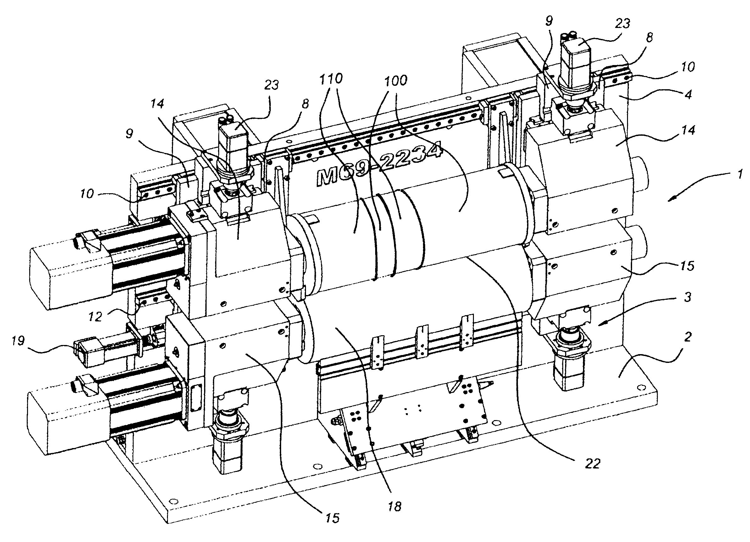
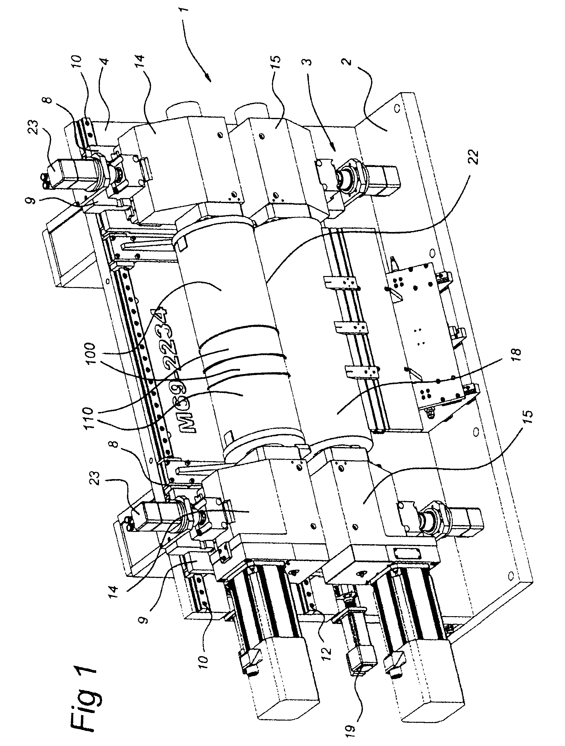
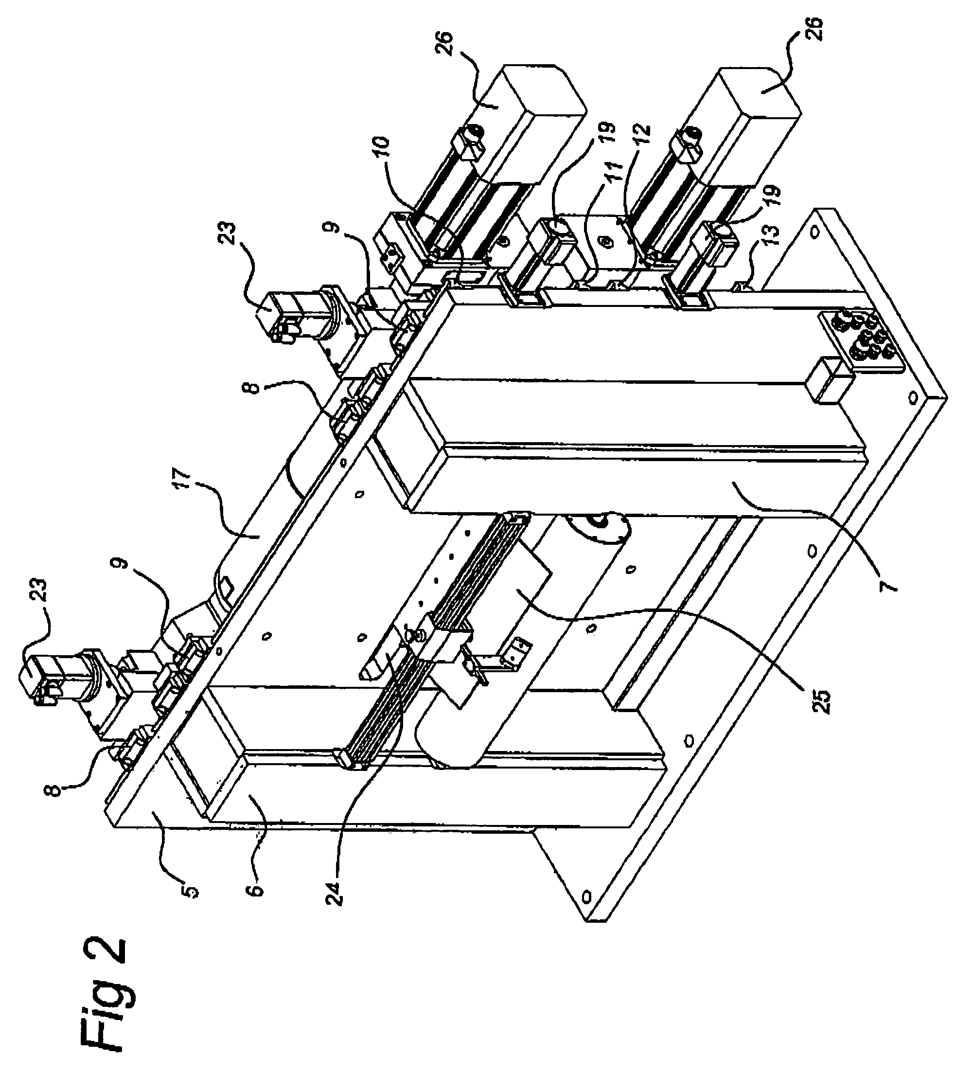
[0037]The rotary installation shown in FIGS. 1 to 4 has a frame that is indicated in its entirety by 1 and essentially consists of the base 2 and the flat plate 3. The flat plate 3 has a flat front face 4 and a flat rear face 5. The stiffening columns 6, 7, which extend as far as the base plate 2, are fixed to the flat rear surface 5.

[0038]Two pairs of vertical guide rails 8, 9 are mounted on the front 4 of the plate 3. The guide rails 8, 9 of each pair are joined to one another and supported on the horizontal guide rails 10-13 such that they can be moved.

[0039]Two heads 14, 15 are fitted on each pair of vertical guide rails. A stab axle 16 is rotatably supported in each of these heads. The stub axles 16 are of truncated cone shape, as can be seen in FIG. 4. The rollers 17, 18 are supported on, in each case, two stub axles 16 located opposite one another, as shown in FIG. 1.

[0040]In connection with installing and, respectively, removing the rollers, the heads 14, 15 are moved apart ...


PUM

PropertyMeasurementUnit
heightaaaaaaaaaa
length dimensionaaaaaaaaaa
width dimensionaaaaaaaaaa

Abstract

A rotary installation comprises a frame, a pair of rollers that define a pinch, a mount supporting the rollers on the frame, an adjuster for moving the mount and the rollers with respect to the frame as well as a drive for making the rollers rotate. The frame has an essentially flat shape determined by two main faces facing away from one another, on one of which main faces the rollers and mount are located.

Description

CROSS-REFERENCE TO RELATED APPLICATIONS[0001]This application is a National Stage of Dutch Patent Application No. 1,024,915, filed Jan. 12, 2003, the contents of which are incorporated by reference herein in its entirety.STATEMENT REGARDING FEDERALLY SPONSORED RESEARCH OR DEVELOPMENT[0002]Not ApplicableTHE NAMES OF THE PARTIES TO A JOINT RESEARCH AGREEMENT[0003]Not ApplicableINCORPORATION-BY-REFERENCE OF MATERIAL SUBMITTED ON A COMPACT DISC[0004]Not ApplicableBACKGROUND OF THE INVENTION[0005]1. Field of the Invention[0006]The invention relates to an installation for making a cut, crease or relief and the like in a sheet of material, such as cardboard, comprising a frame, a pair of rollers that define a pinch between them and the roller surface of which has relatively high surface portions and relatively low surface portions, such as cutting edges and / or edges for making a crease in the sheet of material when feeding it through the pinch, mounting means for supporting the rollers on ...

Claims


Application Information

Patent Timeline
Patent Type & Authority Patents(United States)
IPC IPC(8): B23D25/12B21B13/02B21B31/02B21B31/08B21B35/06B23D35/00B26D7/26B31F1/10B41F13/30
CPCB21B31/02B23D35/008B26D7/2621B26D7/265B31F1/10B41F13/30B21B13/02B21B31/08B21B35/06B21B2031/023B21B2031/026B41P2213/734B41P2213/804Y10T83/483Y10T83/4833
Inventor MADERN, JEAN HENRY ROBERT
Owner MADERN JEAN HENRY ROBERT
Why Eureka
Try Eureka