Hall effect element having a wide cross shape with dimensions selected to result in improved performance characteristics

a technology of cross-sectional shape and wide cross-sectional shape, which is applied in the direction of magnetic sensor geometrical arrangement, instruments, transistors, etc., can solve the problems of reducing response time and low capacitan

Active Publication Date: 2013-01-22
ALLEGRO MICROSYSTEMS INC
View PDF10 Cites 23 Cited by
  • Summary
  • Abstract
  • Description
  • Claims
  • Application Information

AI Technical Summary

Benefits of technology

[0014]The present invention provides a Hall effect element having a shape selected to result in a smaller area than a square Hall effect element, while retaining good sensitivity and low resistance like a square Hall effect element.

Problems solved by technology

Less area also tends to result in lower capacitance, which tends to reduce response time.

Method used


Image

  • Hall effect element having a wide cross shape with dimensions selected to result in improved performance characteristics
  • Hall effect element having a wide cross shape with dimensions selected to result in improved performance characteristics
  • Hall effect element having a wide cross shape with dimensions selected to result in improved performance characteristics

Examples


Embodiment Construction

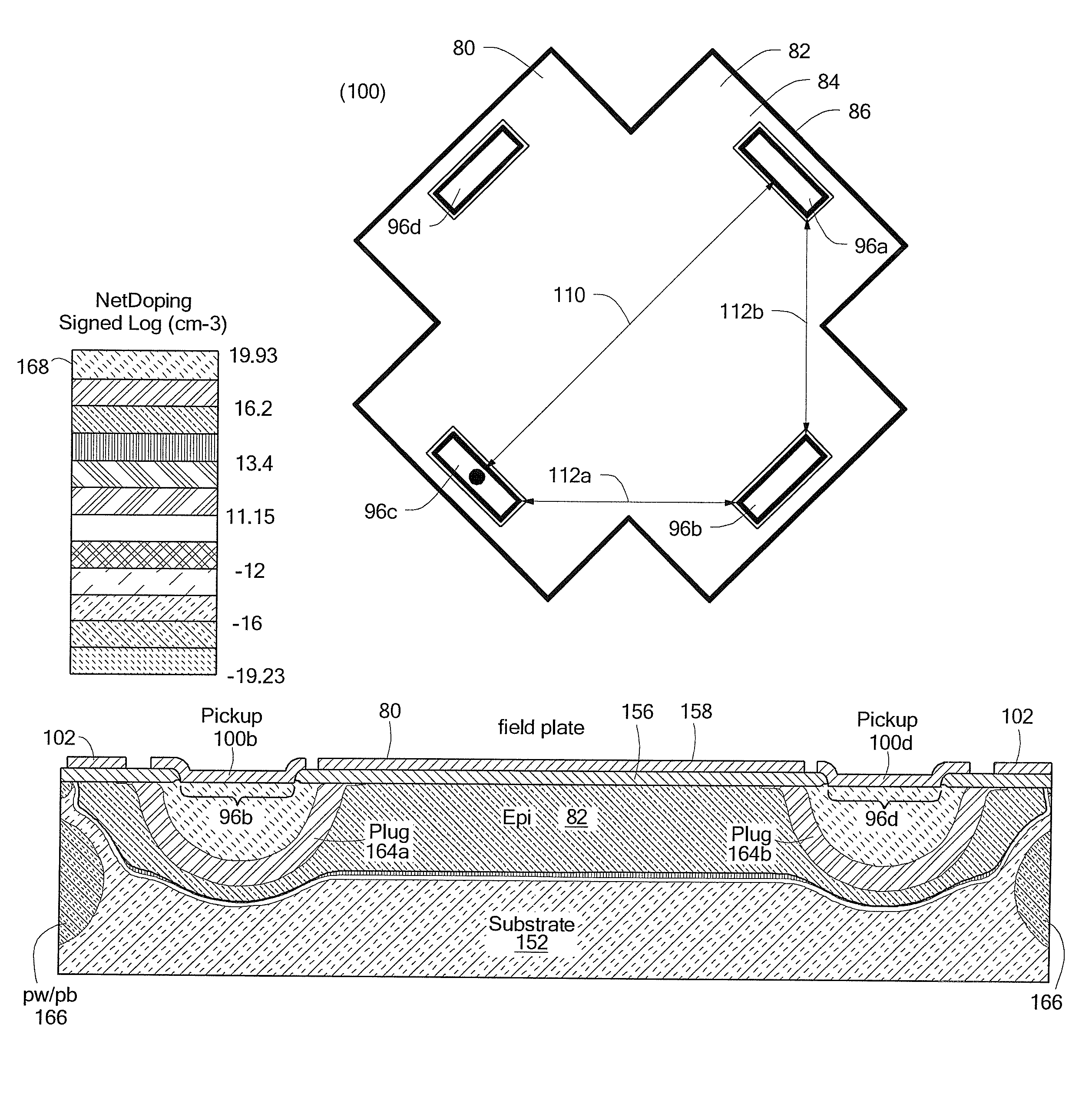
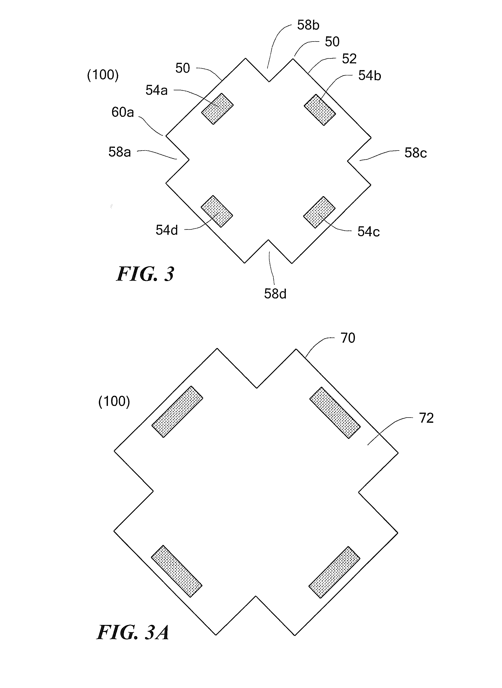
[0025]Referring now to FIG. 3, an exemplary Hall effect element 50 has a Hall plate 52 with a perimeter and four electrical contacts 54a-54d. The perimeter of the Hall plate 52 has particular regions and characteristics described more fully below in conjunction with FIGS. 3B and 3C.

[0026]As will become apparent from discussion below in conjunction with FIG. 4, in a top view, a field plate (not shown) of the Hall effect element 50 in on top of the Hall plate 52. In some embodiments, the perimeter of the Hall plate 52 has essentially the same size and shape as a perimeter of the field plate. Therefore, the entire Hall effect element 50 that includes the Hall plate 52 having the perimeter and the features described below in conjunction with FIGS. 3B and 3C can apply to the perimeter of the Hall plate (epi region) and to the perimeter of the field plate.

[0027]In some other embodiments, a perimeter of the field plate can have a shape different than that of the perimeter of the Hall plate...


PUM


Abstract

A Hall effect element includes a Hall plate having geometric features selected to result in a highest ratio of a sensitivity divided by a plate resistance. The resulting shape is a so-called “wide-cross” shape.

Description

CROSS REFERENCE TO RELATED APPLICATIONS[0001]Not Applicable.STATEMENT REGARDING FEDERALLY SPONSORED RESEARCH[0002]Not Applicable.FIELD OF THE INVENTION[0003]This invention relates generally to Hall effect magnetic field sensing elements and, more particularly, to a Hall effect element having a Hall plate with particular shape and other characteristics selected to result in improved performance characteristics.BACKGROUND OF THE INVENTION[0004]Hall effect magnetic field sensing elements are known. As is known, a Hall effect element includes a so-called “Hall plate,” which is most often an epi region (i.e., layer) upon a substrate. An epi region will be understood to have a medium amount of doping, described more fully below. Above the epi region is a field plate having generally the same outline or perimeter as the Hall plate. The field plate is made of metal or polysilicon. Between the Hall plate and the field plate is disposed an isolation layer, for example, a field oxide or a nitr...

Claims


Application Information

Patent Timeline
Patent Type & Authority Patents(United States)
IPC IPC(8): H01L29/82
CPCG01R33/07G01R33/0005
Inventor WANG, YIGONG
Owner ALLEGRO MICROSYSTEMS INC
Why Eureka
Try Eureka