Exhaust purification apparatus for an engine

a technology for purifying apparatus and exhaust, which is applied in mechanical equipment, machines/engines, separation processes, etc., can solve the problems of deteriorating operative performance, increasing the exhaust pressure of the engine, and increasing the pressure loss, so as to reduce the bias distribution of ammonia, increase the exhaust temperature, and reduce the effect of deterioration

Inactive Publication Date: 2013-01-29
MITSUBISHI FUSO TRUCK AND BUS CORPORATION
View PDF17 Cites 20 Cited by
  • Summary
  • Abstract
  • Description
  • Claims
  • Application Information

AI Technical Summary

Benefits of technology

[0007]The invention has been made in light of the above problems. An object of the present invention is to provide an exhaust purification apparatus for an engine, which is capable of achieving both the acceleration of dispersion and atomization of an auxiliary agent and the inhibition of an increase in engine exhaust pressure at a high level, and thereby delivering good purification performance.

Problems solved by technology

At the same time, the increase of the fin angle changes the exhaust flow direction at a steep angle, leading to an increase in pressure loss.
This results in an increase in exhaust pressure of the engine, which causes a deterioration in operative performance.
Such a phenomenon, too, becomes a factor in hindrance to the dispersion and atomization of the urea aqueous solution.
In this respect, there is still room for improvement in the exhaust purification apparatus disclosed in Patent Document 1 because there is a trade-off relationship between the acceleration of dispersion and atomization of the urea aqueous solution and the inhibition of an increase in engine exhaust pressure, and it is impossible to achieve both of these two at a high level.

Method used


Image

  • Exhaust purification apparatus for an engine
  • Exhaust purification apparatus for an engine
  • Exhaust purification apparatus for an engine

Examples


Embodiment Construction

[0024]An exhaust purification apparatus for an engine according to a first embodiment of the present invention will be described below in details with referenced to the drawings.

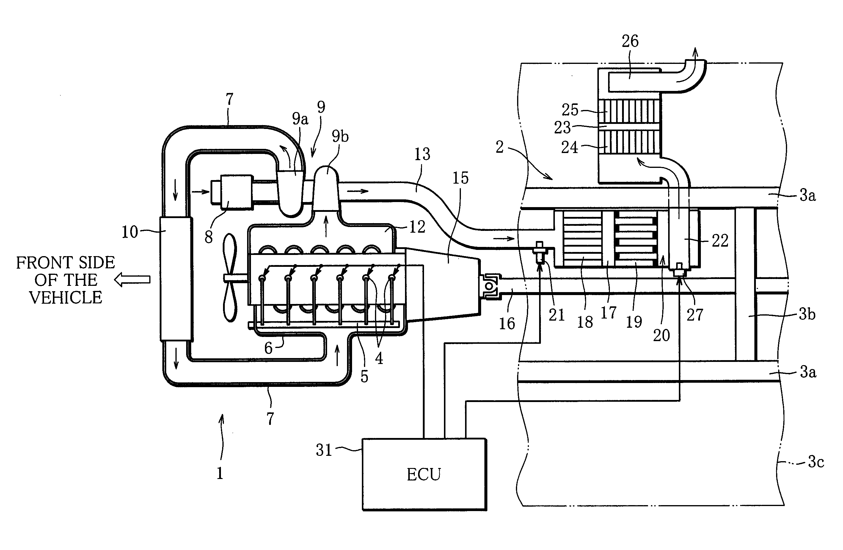
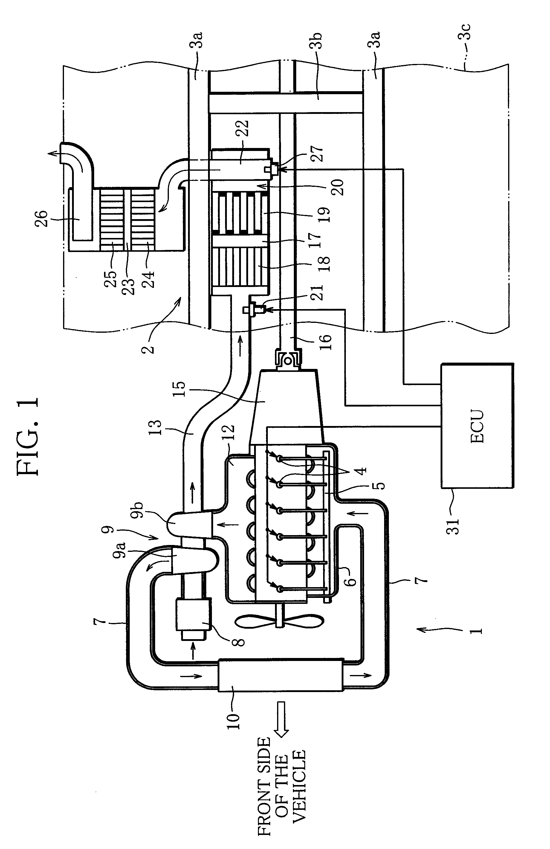
[0025]FIG. 1 is a view showing an entire configuration of the exhaust purification apparatus for an engine according to the first embodiment. An engine 1 is an in-line six-cylinder diesel engine. The engine 1 and an exhaust purification apparatus 2 of the first embodiment are installed in a truck. FIG. 1 schematically shows the engine 1 and the exhausts purification apparatus 2 in the same layout as in an actual placement in the truck, and partially shows an underfloor area of the truck. In the following descriptions, a longitudinal direction and a horizontal direction are defined on the basis of a vehicle.

[0026]The truck employs a chassis structure with a ladder frame. The ladder frame is constructed by connecting a pair of right and left side rails 3a to each other, which extend in an entire longitudinal d...


PUM

PropertyMeasurementUnit
diametersaaaaaaaaaa
areaaaaaaaaaaa
pressure lossaaaaaaaaaa

Abstract

An exhaust purification apparatus for an engine has a first casing (17) that is interposed in an exhaust path (13); a second casing (23) that is set downstream of the first casing (17) and contains an exhaust purification device (24); a connecting pipe (22, 41, 51) that connects the first casing and the second casing (23) to each other and includes an insertion portion that is inserted in the first casing (17); and an injection nozzle (27, 52) that has a tip end inserted in the connecting pipe (22, 41, 51) and injects an auxiliary agent from the tip end. The insertion portion of the connecting pipe (22, 41, 51) is provided with a plurality of through-holes (22a, 41a, 41b, 51a) connecting the inside and the outside of the connecting pipe (22, 41, 51), so that the exhaust gas contained in the first casing (17) is introduced into the connecting pipe (22, 41, 51) through the through-holes and guided towards the second casing (23).

Description

TECHNICAL FIELD[0001]The present invention relates to an exhaust purification apparatus for an engine, and more specifically, to an exhaust purification apparatus in which an auxiliary agent is injected from an injection nozzle into exhaust gas flowing through an exhaust passage, and is supplied to an exhaust purification device.BACKGROUND ART[0002]For example, an exhaust purification apparatus with an SCR catalyst (selective reduction type NOx catalyst) has been known as one in which an auxiliary agent is injected into exhaust gas and supplied to an exhaust purification device. As is well known, the SCR catalyst needs NH3 (ammonia) for reducing NOx contained in exhaust gas. In the exhaust purification system, a urea aqueous solution is injected as a reducing agent acting as an auxiliary agent from an injection nozzle disposed upstream of the SCR catalyst interposed in the exhaust passage. The NH3 produced by the urea aqueous solution being hydrolyzed by exhaust heat and water vapor...

Claims


Application Information

Patent Timeline
Patent Type & Authority Patents(United States)
IPC IPC(8): F01N3/00F01N3/02F01N1/00F01N3/10
CPCB01D53/90F01N13/009F01N3/0253F01N3/035F01N3/106F01N3/2066F01N3/24F01N3/2882F01N3/2892F01N13/08F01N13/0097B01D53/9431B01D53/9477B01D2251/2067F01N2470/02F01N2610/02Y02T10/24Y02T10/12B01D53/94F01N3/28F01N3/36
Inventor YAMAZAKI, SATOSHITAKEDA, YOSHINAKAFUJITA, HIROAKIHIRANUMA, SATOSHISAITO, SHINICHI
Owner MITSUBISHI FUSO TRUCK AND BUS CORPORATION
Why Eureka
Try Eureka