
Gas sensor control apparatus and method

a technology for gas sensors and control apparatuses, applied in the direction of instruments, liquid/fluent solid measurements, electrochemical variables of materials, etc., can solve the problems of nox sensors but also any other types of sensors, and change the so as to achieve uniform stabilization time of gas sensors

Active Publication Date: 2013-01-29
NGK SPARK PLUG CO LTD
View PDF6 Cites 4 Cited by
  • Summary
  • Abstract
  • Description
  • Claims
  • Application Information

AI Technical Summary

Benefits of technology

[0005]It is therefore an object of the present invention to provide an apparatus and method for controlling a gas sensor so as to ensure a uniform stabilization time of the gas sensor at sensor startup.

Problems solved by technology

The above-proposed conventional preliminary drive control presents a problem that the stabilization time of the gas sensor changes depending on the H2O concentration due to the application of the higher voltage than that in the normal drive control.
This problem arises in not only the NOx sensor but also any other types of sensors using oxygen pumping cells.

Method used


Image

  • Gas sensor control apparatus and method
  • Gas sensor control apparatus and method
  • Gas sensor control apparatus and method

Examples


first embodiment

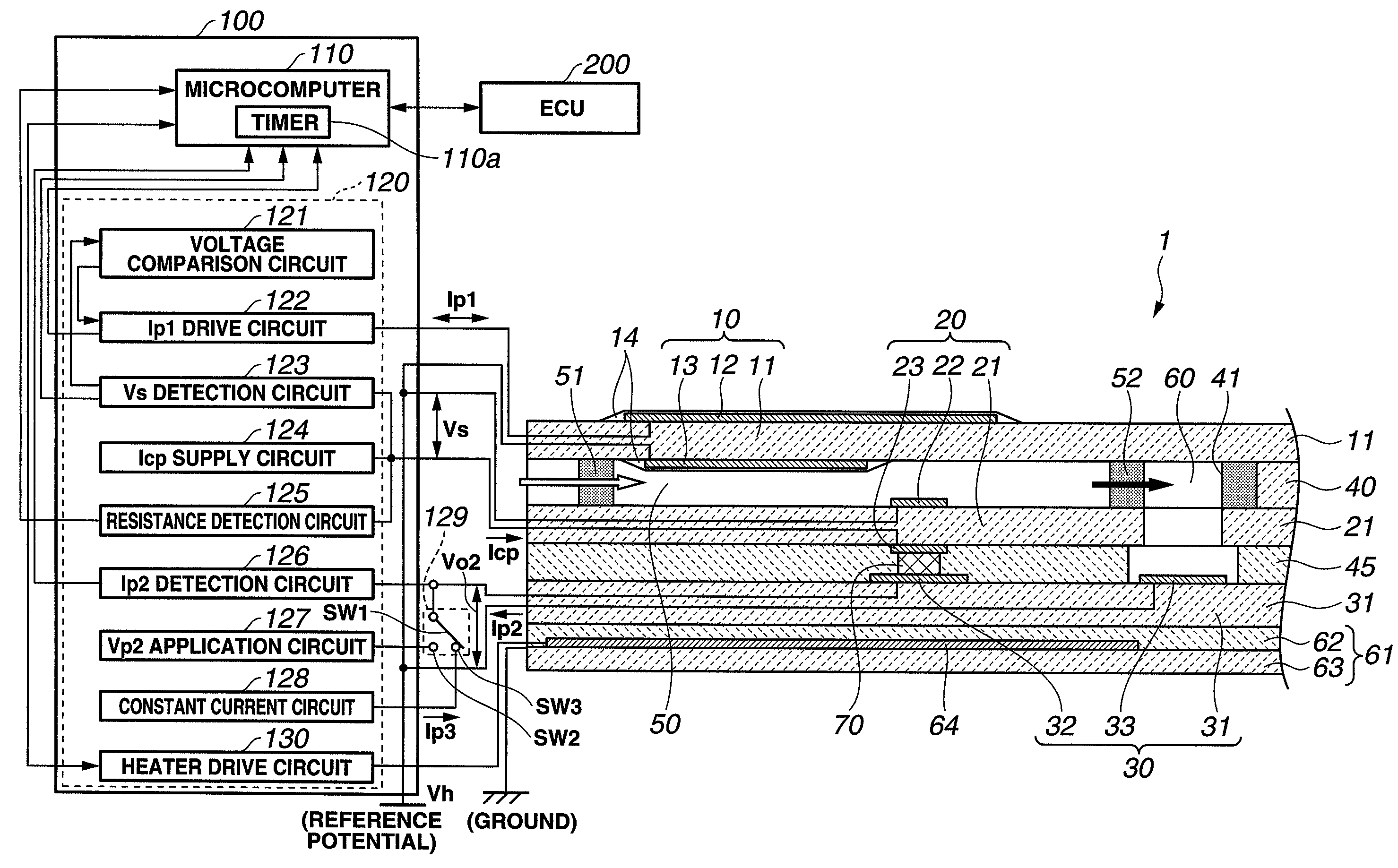
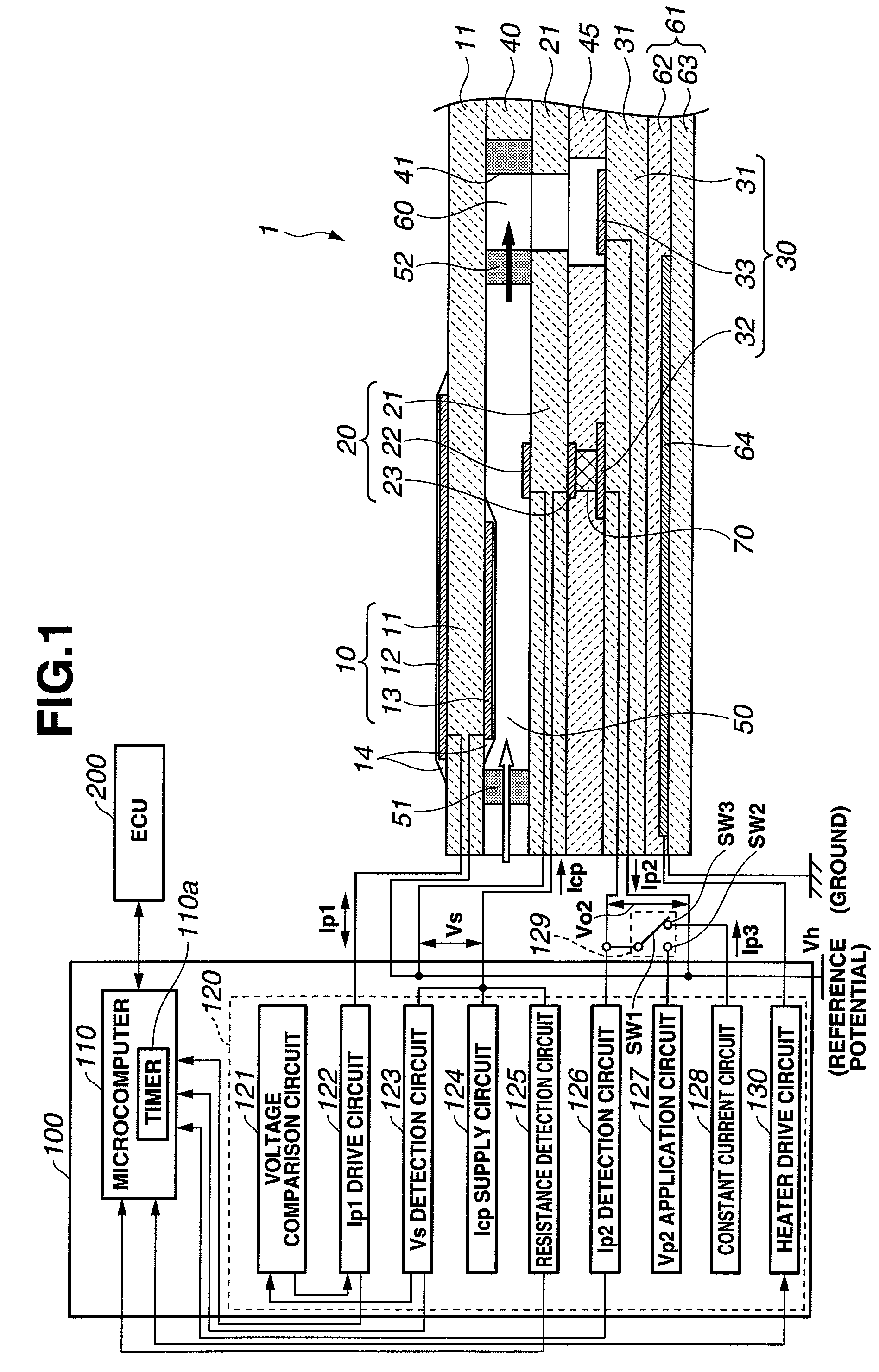
[0017]Referring to FIG. 1, a gas sensor system according to the first embodiment of the present invention is designed for use in an internal combustion engine and includes a gas sensor having a sensor element 1 and a heater element 61 accommodated in a housing and mounted to an exhaust pipe of the engine to detect nitrogen oxide (NOx) in an engine exhaust gas and a sensor control apparatus 100 located separately from and electrically connected to the gas sensor (sensor element 1 and heater element 61) via lead wires to control the operations of the gas sensor and to determine the concentration of NOx in the exhaust gas based on the output of the gas sensor (sensor element 1).

[0018]The sensor element 1 has a rectangular plate shape formed with oxygen ion conducting solid electrolyte layers 11, 21 and 31 (oxygen ion conductors), insulating layers 40 and 45, porous electrodes 12, 13, 22, 23, 32 and 33 and porous gas diffusion control members 51 and 52. The solid electrolyte layers 11, ...

second embodiment

[0061]A gas sensor system with a gas sensor and a sensor control apparatus according to the second embodiment of the present invention is structurally similar to that of the first embodiment, except for the configurations of the Vp2 application circuit 127 and the switching circuit 129 and the processing operations of the microcomputer 110.

[0062]With the supply of the constant current Ip3 from the constant current circuit 128 to the Ip2 cell 30 during the preliminary drive control, the voltage (electromotive force) between the porous electrodes 32 and 33 increases as the oxygen concentration in the second measurement chamber 60 becomes decreased by the oxygen pumping action of the Ip2 cell 30. If the supply of the constant current Ip3 to the Ip2 cell 30 is continued in such a condition, there is a fear of blackening of the solid electrolyte layer 31 and, by extension, breakage of the Ip2 cell 30 due to overvoltage between the porous electrodes 32 and 33 during the preliminary drive ...


PUM

PropertyMeasurementUnit
time periodaaaaaaaaaa
constant drive voltage Vp2aaaaaaaaaa
constant electric current Ip3aaaaaaaaaa

Abstract

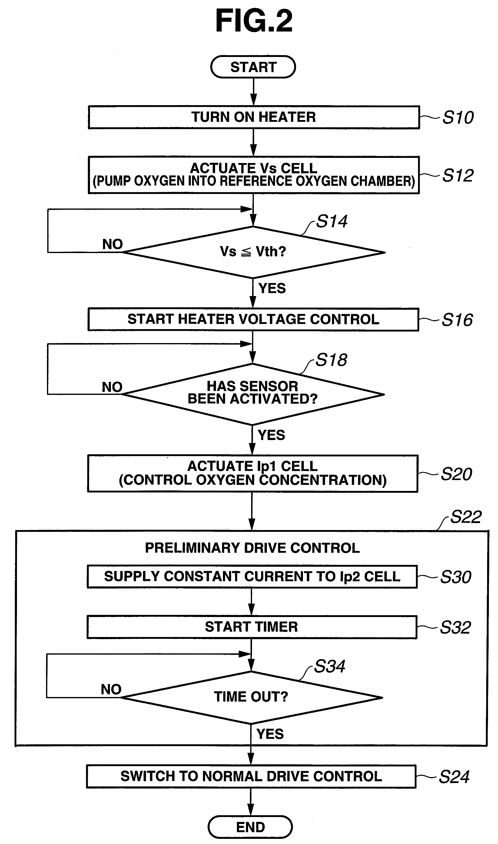
There is provided a control apparatus for a gas sensor, which has a sensor element equipped with first and second oxygen pumping cells. The sensor control apparatus is configured to drive the first oxygen pumping cell to adjust the oxygen concentration of gas under measurement, drive the second oxygen pumping cell to produce a flow of electric current according to the amount of oxygen pumped out of the oxygen concentration adjusted gas by the second oxygen pumping cell, perform specific drive control to control the amount of oxygen pumped by the second oxygen pumping cell to a predetermined level after startup of the sensor element and before the application of the drive voltage between the electrodes of the second oxygen pumping cell.

Description

BACKGROUND OF THE INVENTION[0001]The present invention relates to an apparatus and method for controlling a gas sensor, which is capable of detecting a specific gas component in a gas under measurement, and more particularly to control of the gas sensor at startup.[0002]Various gas sensors are used to measure the concentration of a specific gas component e.g. nitrogen oxide (NOx) or ammonium in a gas under measurement such as an exhaust gas from an internal combustion engine. For example, there is known a NOx sensor that includes a sensor element equipped with an oxygen concentration detection cell and first and second oxygen pumping cells, each of which has an oxygen ion conducting solid electrolyte layer and a pair of porous electrodes arranged on the solid electrolyte layer, to define first and second measurement chambers. When a gas under measurement first flows into the first measurement chamber, the first oxygen pumping cell pumps oxygen in or out of the first measurement cham...

Claims


Application Information

Patent Timeline
Patent Type & Authority Patents(United States)
IPC IPC(8): G01N27/26G01N27/417
CPCG01N27/419
Inventor TERAMOTO, SATOSHIONOGI, HIROTAKASHIOTANI, KOJIKATO, KENJIKAWAI, TAKASHI
Owner NGK SPARK PLUG CO LTD
Learn More