Optical network and optical signal modulation method thereof

a technology of optical signal and optical network, applied in the field of optical network, can solve problems such as not being so perfect, and achieve the effect of reducing the interference between the two rayleigh backscattering noises and the upstream signal

Active Publication Date: 2013-01-29
IND TECH RES INST
View PDF6 Cites 4 Cited by
  • Summary
  • Abstract
  • Description
  • Claims
  • Application Information

AI Technical Summary

Benefits of technology

[0009]Accordingly, the present disclosure is directed to an optical network capable of changing the frequency of an optical signal and an optical signal modulation method thereof, wherein interference of Rayleigh backscattering noises of a continuous carrier wave and an upstream signal to the upstream signal is reduced.
[0012]According to exemplary embodiments of the present disclosure, a frequency modulation technique is adopted to make the frequency of an upstream signal different from that of a Rayleigh backscattering noise of the upstream signal and that of a Rayleigh backscattering noise of a continuous carrier wave. Thereby, interference of the two Rayleigh backscattering noises to the upstream signal is reduced.

Problems solved by technology

However, actually, it may not be so perfect.

Method used


Image

  • Optical network and optical signal modulation method thereof
  • Optical network and optical signal modulation method thereof
  • Optical network and optical signal modulation method thereof

Examples


Embodiment Construction

[0018]Reference will now be made in detail to the present preferred embodiments of the disclosure, examples of which are illustrated in the accompanying drawings. Wherever possible, the same reference numbers are used in the drawings and the description to refer to the same or like parts.

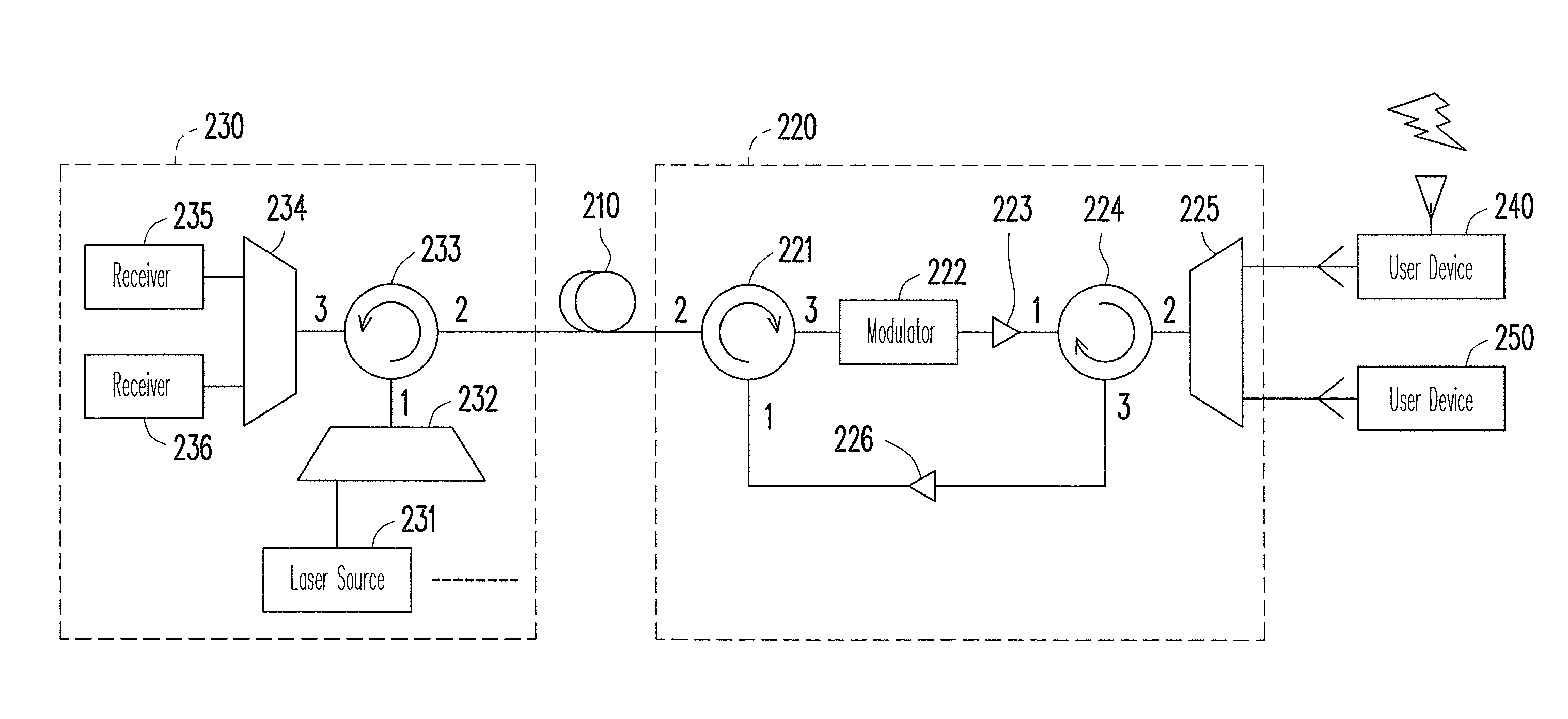
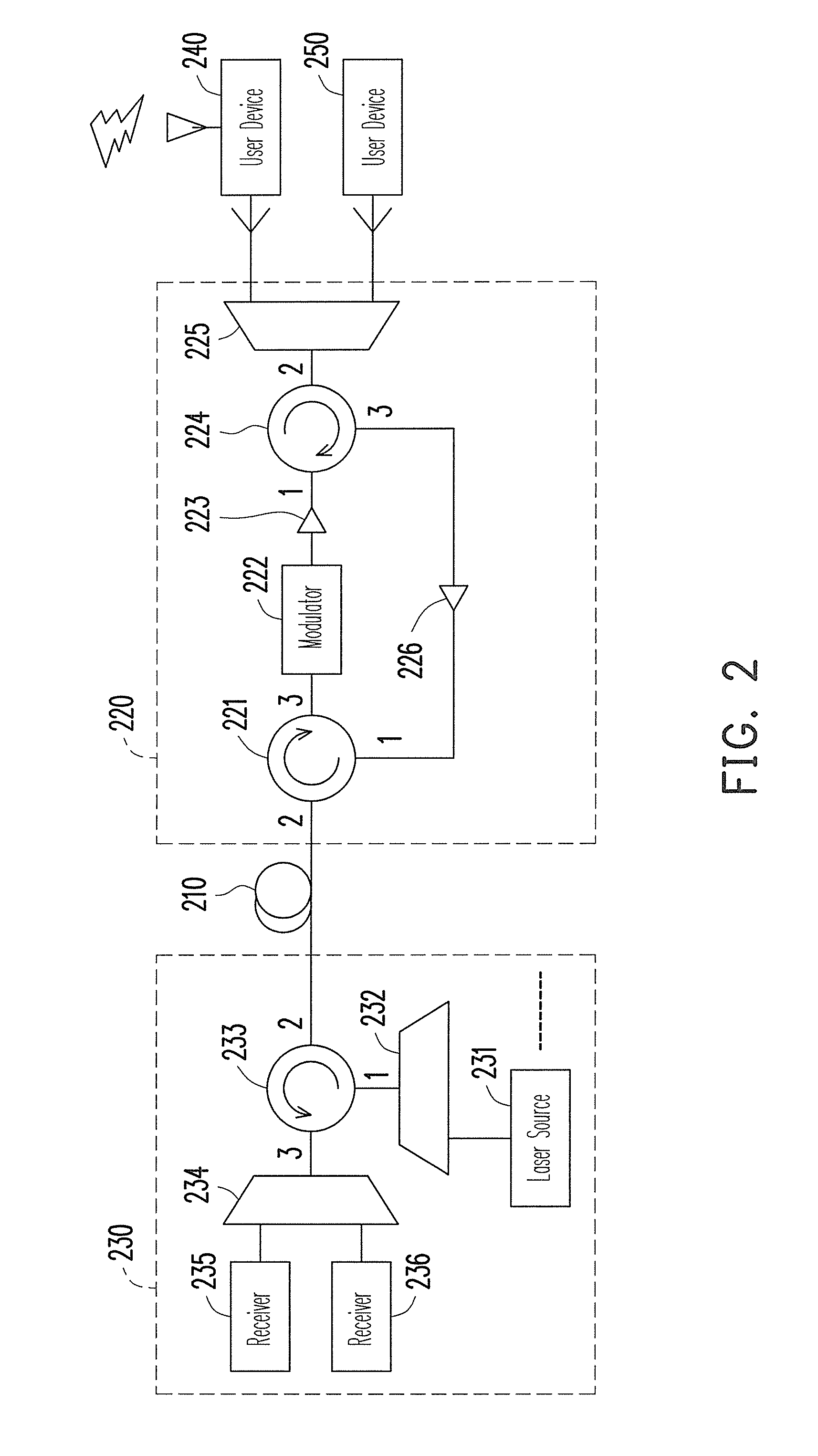
[0019]FIG. 2 is a schematic diagram of an optical network according to an embodiment of the present disclosure, and FIG. 3 is a flowchart of an optical signal modulation method executed by this optical network. The optical network includes a head-end 230, an optical fiber 210, and a remote node (RN) 220. The head-end 230 includes a laser source 231, wavelength division multiplexers (WDMs) 232 and 234, an optical circulator (OC) 233, and receivers 235 and 236. The RN 220 includes OC 221 and 224, a modulator 222, optical amplifiers 223 and 226, and a WDM 225. The WDMs 225, 232, and 234 may be implemented by using arrayed waveguide gratings (AWGs). Each of the OCs 221, 224, and 233 has 3 input / output p...


PUM


Abstract

An optical network and an optical signal modulation method thereof are provided. The optical network includes an optical fiber and a remote node (RN). The RN receives a continuous carrier wave from the optical fiber and modulates the continuous carrier wave to generate a first frequency offset carrier wave The frequency of the first frequency offset carrier wave is different from that of the continuous carrier wave. A first user device re-modulates and loads data to the first frequency offset carrier wave to generate a first upstream signal. The frequency of the first upstream signal is the same as that of the first frequency offset carrier wave. The RN inputs the first upstream signal into the optical fiber.

Description

CROSS-REFERENCE TO RELATED APPLICATION[0001]This application claims the priority benefit of Taiwan application serial no. 98138084, filed on Nov. 10, 2009. The entirety of the above-mentioned patent application is hereby incorporated by reference herein and made a part of specification.BACKGROUND[0002]1. Field of the Disclosure[0003]The present disclosure relates to an optical network capable of changing the frequency of an optical signal and an optical signal modulation method thereof.[0004]2. Description of Related Art[0005]FIG. 1 is a schematic diagram of a conventional optical network. The optical network includes a head-end 110, an optical fiber 120, and a wavelength division multiplexer (WDM) 130. The head-end 110 includes a plurality of laser sources. A single laser source 111 is demonstratively illustrated in FIG. 1. The laser source 111 provides a continuous carrier wave 151. The WDM 112 combines and outputs the continuous carrier waves emitted by all the laser sources thro...

Claims


Application Information

Patent Timeline
Patent Type & Authority Patents(United States)
IPC IPC(8): H04J14/00
CPCH04B10/2587H04J14/0282H04J2014/0253
Inventor YEH, CHIEN-HUNGCHOW, CHI-WAI
Owner IND TECH RES INST
Why Eureka
Try Eureka