Dual air duct for front end of vehicle

a dual-layer, front-end technology, applied in vehicle heating/cooling devices, transportation and packaging, propulsion parts, etc., can solve the problems of increasing fuel consumption and reducing fuel consumption, and achieve the effects of reducing fuel consumption, improving cooling performance of the vehicle, and high engine power

Active Publication Date: 2013-02-05
HYUNDAI MOTOR CO LTD +1
View PDF18 Cites 18 Cited by
  • Summary
  • Abstract
  • Description
  • Claims
  • Application Information

AI Technical Summary

Benefits of technology

[0012]Various aspects of the present invention are directed to provide a dual air duct of the front end in a vehicle that improves the cooling performance with high engine power, decrease the fuel consumption, and secures sufficient cooling performance for the engine by improving the cooling performance of the condenser and the intercooler and minimizing reduction of the cooling performance of the radiator, without restricting design and deteriorating the front appearance of the vehicle.
[0023]An opening disposed in a middle portion of the guide may be smaller than the rear opening so as to increase flow speed of the running wind.
[0031]According to an exemplary embodiment of the present invention as described above, it is possible to improve the cooling performance of the vehicle with high engine power and decrease the fuel consumption while securing sufficient cooling performance for the engine by improving the cooling performance of the condenser and the intercooler.
[0032]Further, the invention has the effect of reducing restriction on design because it has substantially no effect on the design of the front appearance of the vehicle.

Problems solved by technology

Therefore, since it is difficult to sufficiently increase the areas of the holes, cooling performance of the heat sinks, engine cooling, and engine power may decrease fuel consumption may increase.

Method used


Image

  • Dual air duct for front end of vehicle
  • Dual air duct for front end of vehicle
  • Dual air duct for front end of vehicle

Examples


Embodiment Construction

[0041]Reference will now be made in detail to various embodiments of the present invention(s), examples of which are illustrated in the accompanying drawings and described below. While the invention(s) will be described in conjunction with exemplary embodiments, it will be understood that present description is not intended to limit the invention(s) to those exemplary embodiments. On the contrary, the invention(s) is / are intended to cover not only the exemplary embodiments, but also various alternatives, modifications, equivalents and other embodiments, which may be included within the spirit and scope of the invention as defined by the appended claims.

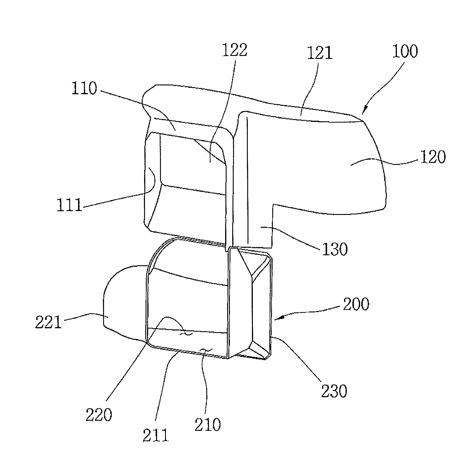
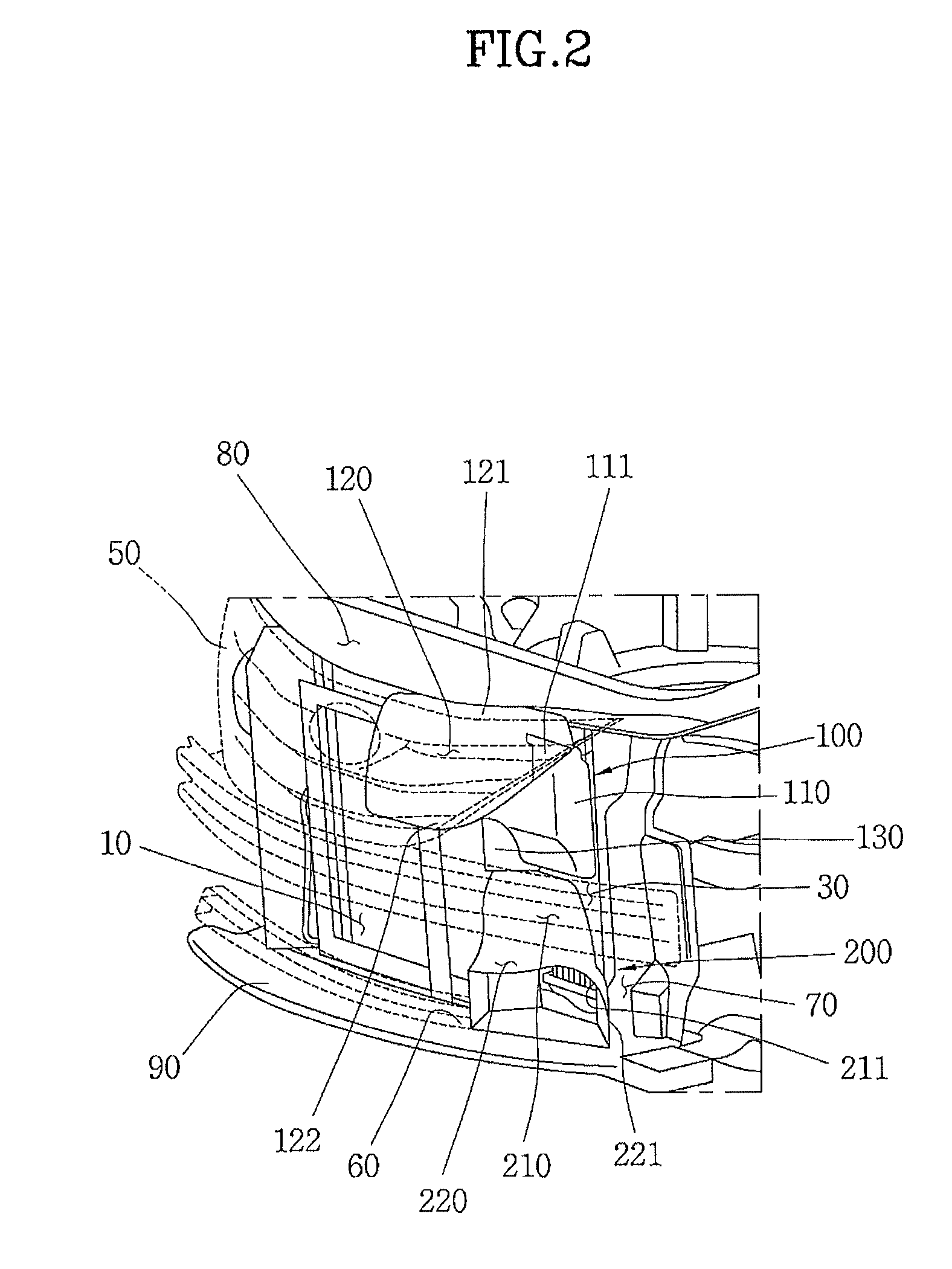
[0042]As shown in the FIGS. 2 and 3, the dual air duct according to an exemplary embodiment of the present invention includes an upper duct 100 and a lower duct 200 disposed in a vertical direction in series.

[0043]Upper duct 100 and lower duct 200 are disposed in front of an intercooler 30.

[0044]Upper duct 100 includes a main body 110...


PUM


Abstract

A dual air duct of a vehicle may include an upper duct that guides running wind flowing outside an intercooler through a radiator grill to upper portion of the intercooler and a lower duct that guides running wind flowing outside the intercooler through a hole of a bumper cover to lower portion of the intercooler.

Description

CROSS-REFERENCE TO RELATED APPLICATIONS[0001]The present application claims priority to Korean Application Number 10-2008-0050145 filed May 29, 2008, the full contents of which are incorporated herein for all purposes by this reference.FIELD OF THE INVENTION[0002]The present invention relates to a dual air duct disposed at the front end in a vehicle that improves cooling performance of an intercooler and a condenser by guiding a running wind that flows into the engine compartment when the vehicle is traveling.BACKGROUND OF THE INVENTION[0003]As shown in FIG. 1, a condenser 10 of a cooling system, a radiator 20 of an engine cooling system, and an intercooler 30 that cools oversupplied air in a turbocharger engine are disposed in the front end of a vehicle to cool the running wind that flows into the engine compartment when the vehicle is traveling.[0004]In general, condenser 10 is disposed at the very front, radiator 20 is disposed closely behind condenser 10, and intercooler 30 is d...

Claims


Application Information

Patent Timeline
Patent Type & Authority Patents(United States)
IPC IPC(8): B60K11/00
CPCB60K11/00B62D25/08
Inventor LEE, JONGHOONNAM, JONGWOO
Owner HYUNDAI MOTOR CO LTD
Why Eureka
Try Eureka