Communication apparatus, program, communication method and communication system
a communication apparatus and program technology, applied in the field of communication apparatus, a program, a communication method and a communication system, can solve problems such as complicated for users having a communication apparatus, and achieve the effect of convenient structur
- Summary
- Abstract
- Description
- Claims
- Application Information
AI Technical Summary
Benefits of technology
Problems solved by technology
Method used
Image
Examples
first example
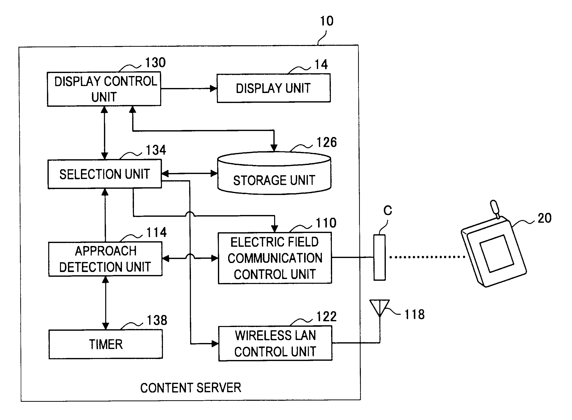
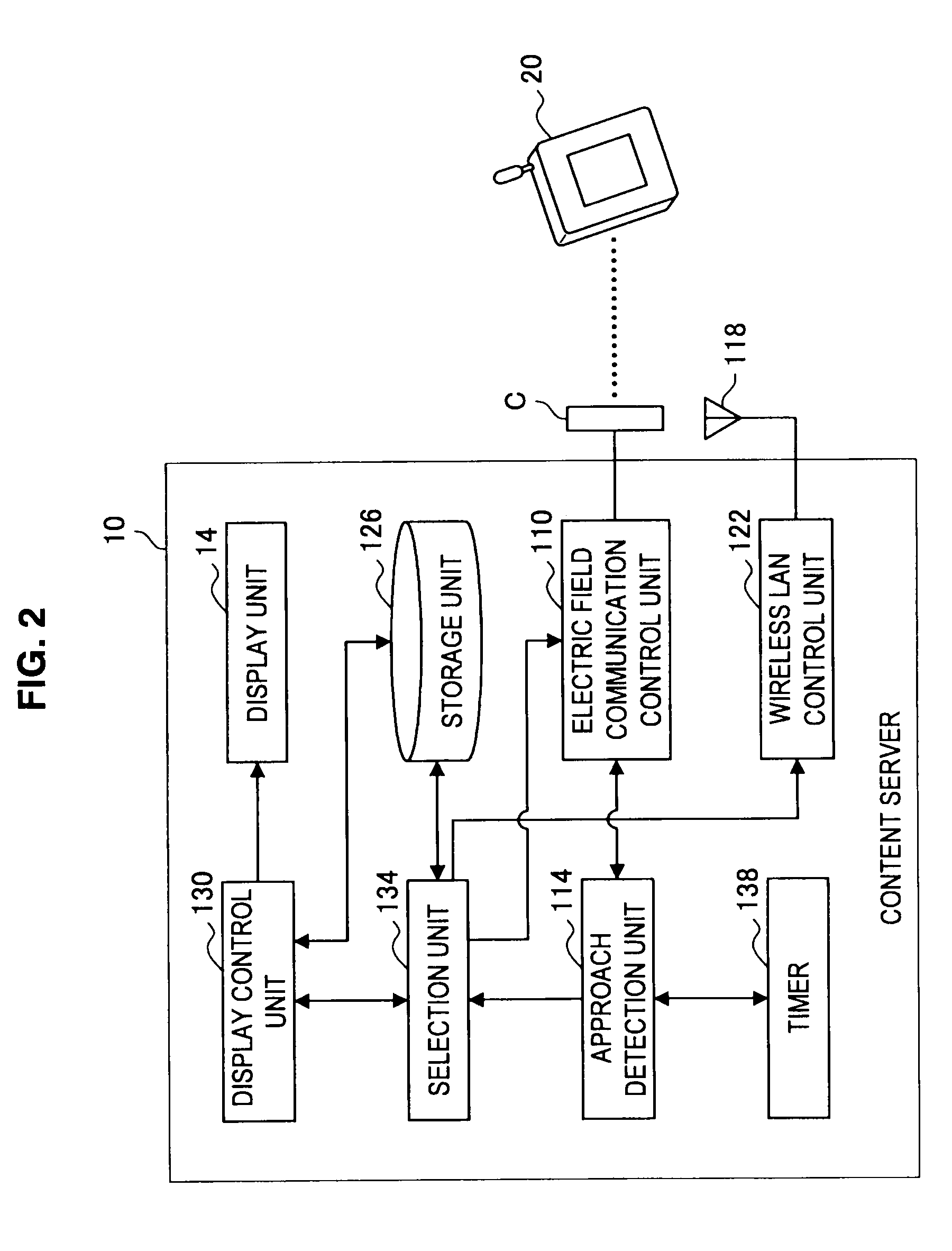
[0060]FIG. 3 is a sequence diagram showing a flow of the operation of the communication system 1 according to the first embodiment. FIG. 3 shows an example in which the content server 10 functions as an initiator and the cell phone 20 functions as a responder, but the content server 10 may function as a responder and the cell phone 20 may function as an initiator. It can be similarly applied to FIGS. 4 and 5.
[0061]At first, as shown in FIG. 3, the electric field coupler C of the content server 10 repeats the transmission of a connection establishment request (C-Req) until the cell phone 20 approaches (S202). Then, when the content server 10 and the cell phone 20 approach each other and the cell phone 20 receives the connection establishment request transmitted from the electric field coupler C of the content server 10 (S204), the cell phone 20 transmits a response (C-ACC) to the connection establishment request (S206). Further, the electric field coupler C of the content server 10 t...
second example
[0066]There has been described above the example in which the content server 10 transmits the count data, but the cell phone 20 may transmit the count data as described below with reference to FIG. 4.
[0067]FIG. 4 is a sequence diagram showing a variant of the operation of the communication system 1 according to the first embodiment. At first, as shown in FIG. 4, the electric field coupler C of the content server 10 repeats the transmission of a connection establishment request (C-Req) until the cell phone 20 approaches (S242). Then, when the content server 10 and the cell phone 20 approach each other and the cell phone 20 receives the connection establishment request transmitted from the electric field coupler C of the content server 10 (S244), the cell phone 20 transmits a response (C-ACC) to the connection establishment request (S246). Further, the electric field coupler C of the content server 10 transmits a confirmation signal (C-Ack) for the response (C-ACC) under control of th...
third example
[0072]There has been described above the example in which the content server 10 transmits the data selected by the selection unit 134 from the electric field coupler C when approaching the cell phone 20 again, but the content server 10 may transmit the data selected by the selection unit 134 via a wireless LAN as described below with reference to FIG. 5.
[0073]FIG. 5 is a sequence diagram showing a variant of the operation of the communication system 1 according to the first embodiment. At first, as shown in FIG. 5, the electric field coupler C of the content server 10 repeats the transmission of a connection establishment request (C-Req) until the cell phone 20 approaches (S274). Then, when the content server 10 and the cell phone 20 approach each other and the cell phone 20 receives the connection establishment request transmitted from the electric field coupler C of the content server 10 (S276), the cell phone 20 transmits a response (C-ACC) to the connection establishment request...
PUM
 Abstract
Description
Claims
Application Information
 - R&D
- Intellectual Property
- Life Sciences
- Materials
- Tech Scout
- Unparalleled Data Quality
- Higher Quality Content
- 60% Fewer Hallucinations
Browse by: Latest US Patents, China's latest patents, Technical Efficacy Thesaurus, Application Domain, Technology Topic, Popular Technical Reports.
© 2025 PatSnap. All rights reserved.Legal|Privacy policy|Modern Slavery Act Transparency Statement|Sitemap|About US| Contact US: help@patsnap.com


