Smart vehicle sensor

a technology of exhaust gas sensor and sensor, applied in the direction of electrical control, fire alarms, instruments, etc., can solve the problems of sensor signal not being usable, sensor signal instability, sensor measurement accuracy, etc., to reduce the light-off time of the sensor, accurate sense the sensed parameter, and improve vehicle diagnostics

Active Publication Date: 2013-02-05
FORD GLOBAL TECH LLC
View PDF9 Cites 5 Cited by
  • Summary
  • Abstract
  • Description
  • Claims
  • Application Information

AI Technical Summary

Benefits of technology

[0003]The inventors herein have recognized the above problems and have devised various approaches to at least partially address them. Thus, in one example, a sensor is provided, the sensor comprising an output responsive to a sensed parameter; and a coded indication of a sensor light-off response for the sensed parameter. The sensor may be an exhaust gas sensor, such as an exhaust gas constituent sensor, and the coded indication of the sensor light-off response may include sensor-specific data particular to, and selected specifically for, the sensor. In this way, because the sensor provides a coded indication of its light-off response, systems using the sensor may be able to account for the manufacturing sensor to sensor variability in the sensed parameter. Therefore, the sensor may be used to accurately sense the sensed parameter even during the warm-up operation of the sensor, before reaching light-off. This can enable the sensor to be used for diagnosing engine and / or emission control system properties earlier in a vehicle drive cycle, for example, thus enabling improved vehicle diagnostics.
[0004]In another example, a method for decreasing the light-off time of a sensor is disclosed. The method comprises receiving sensed parameter data from the sensor, receiving encoded calibration data from the sensor, and adjusting a vehicle operating parameter in response to the sensed parameter data and the encoded calibration data. The encoded calibration data, which may correspond to a limited set of calibration codes indicating a sensor-specific light-off response for the sensed parameter, may be sent from the sensor to an engine control unit during the period after operation begins, but before the sensor reaches a stable light-off temperature. In this manner, the corresponding calibration data may be utilized to correct an otherwise degraded signal, thus reducing the amount of time to obtain useable output from the sensor.

Problems solved by technology

During this time, a sensor signal may be unstable and the sensor measurements may be inaccurate.
As a result, the sensor signal may not be usable until after light-off of the sensor has occurred.

Method used


Image

  • Smart vehicle sensor
  • Smart vehicle sensor
  • Smart vehicle sensor

Examples


Embodiment Construction

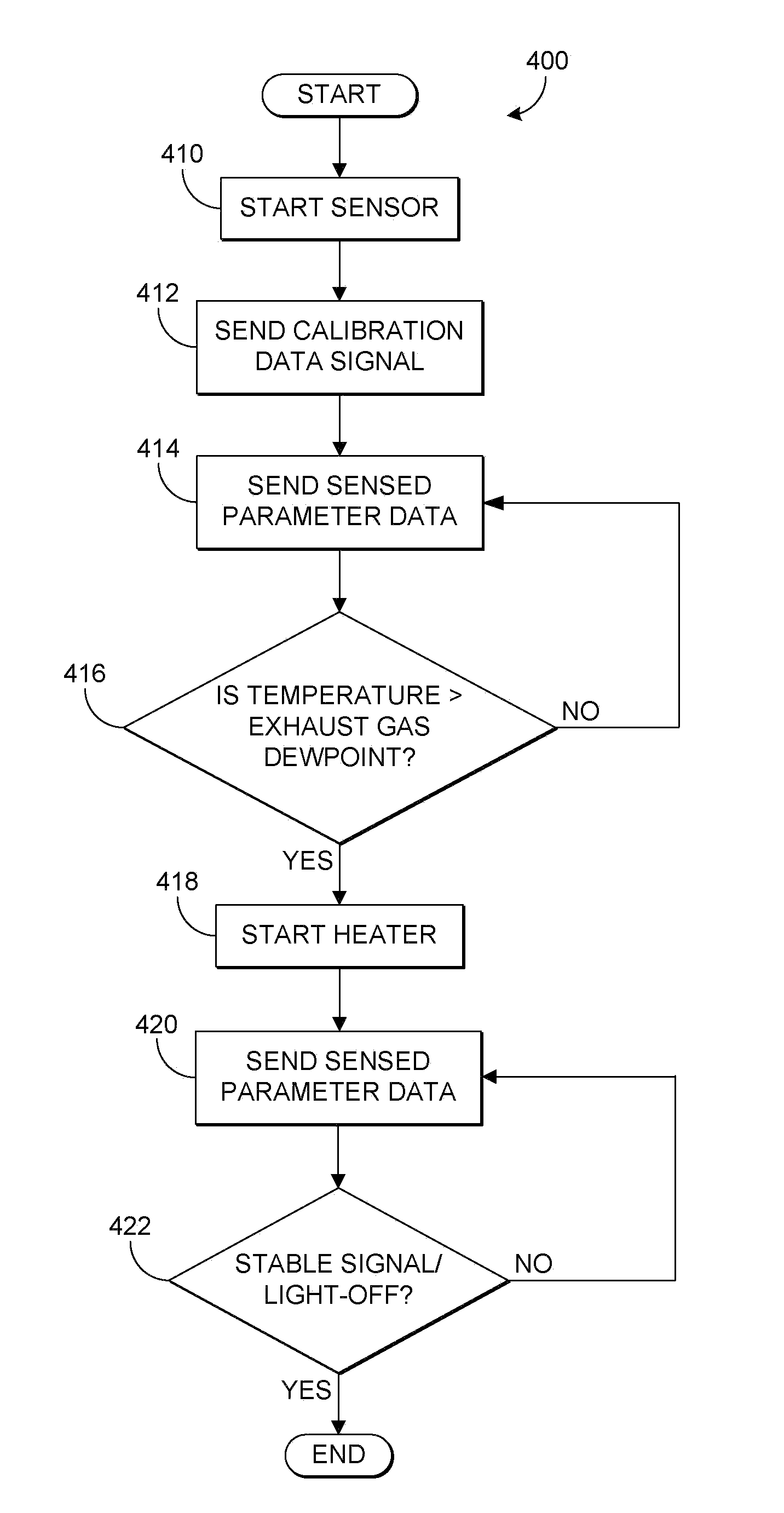
[0015]The following description relates to a method for controlling operation of a vehicle based on a sensor coupled in the exhaust system of the engine. The sensor includes a coded indication of the sensor light-off response, which in one example corresponds to sensor-specific data that is particular to and selected specifically for the sensor. After the sensor operation is started, the sensor may send the coded indication of the sensor light-off response (e.g., calibration data) to an engine control unit (ECU) or another controller via a controller area network (CAN) where it is decoded. The calibration data corresponding to the coded indication may then be applied to output of the sensor corresponding to a sensed parameter, in order to more accurately measure the sensed parameter.

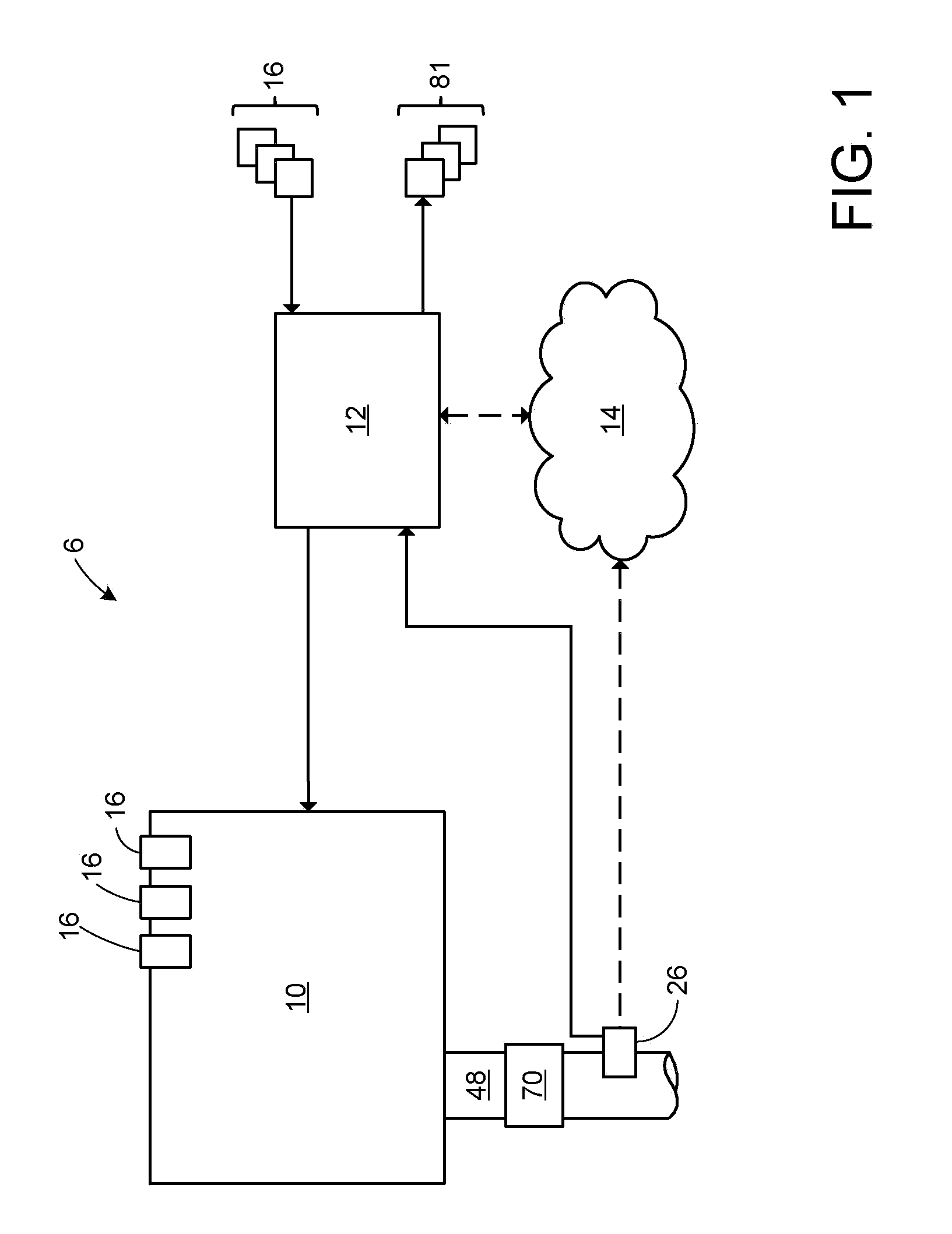
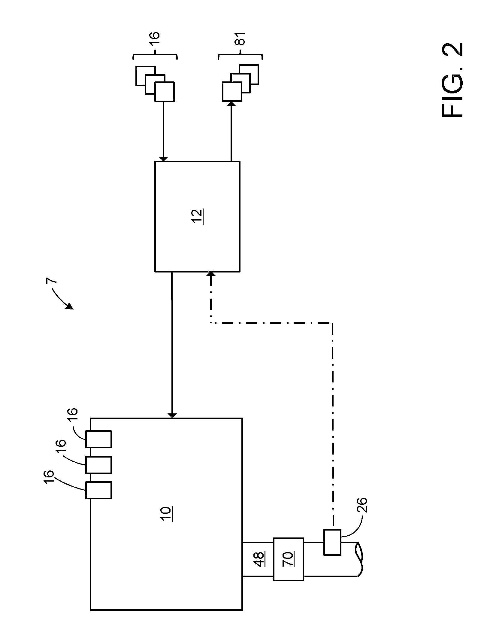
[0016]FIGS. 1-3 show schematic diagrams of a vehicle system 6. The vehicle system 6 includes an engine 10 which may be included in a propulsion system of an automobile, truck, etc. Engine 10 may be contr...


PUM

PropertyMeasurementUnit
temperatureaaaaaaaaaa
light-off temperature responseaaaaaaaaaa

Abstract

Various systems and methods are described for controlling operation of a motor vehicle based on a sensor. One example method comprises receiving sensed parameter data from the sensor, receiving calibration data from the sensor, and adjusting a vehicle operating parameter in response to the sensed parameter data and the calibration data.

Description

TECHNICAL FIELD[0001]The present application relates generally to systems and methods for an exhaust gas sensor for measuring exhaust gas constituents from an internal combustion engine.BACKGROUND AND SUMMARY[0002]Upon cold start of a motor vehicle, there is an amount of time in which components such as exhaust gas constituent sensors warm up to their respective operating temperatures (e.g, light-off time). During this time, a sensor signal may be unstable and the sensor measurements may be inaccurate. In particular, while manufacturing processes may be developed that enable the sensor to sensor variation to be maintained at an acceptably low level for the sensor performance upon reaching light-off, sensor to sensor variation may have a significant impact on sensor response during the light-off time. As a result, the sensor signal may not be usable until after light-off of the sensor has occurred.[0003]The inventors herein have recognized the above problems and have devised various ...

Claims


Application Information

Patent Timeline
Patent Type & Authority Patents(United States)
IPC IPC(8): G01N25/00
CPCF02D41/064F02D41/146F02D41/1494F02D41/26F02D41/2454F02D41/2432F02D41/2474F02D2200/021
Inventor WEBER, DAVE CHARLESKUBINSKI, DAVID JOHNVAN NIEUWSTADT, MICHIEL J.
Owner FORD GLOBAL TECH LLC
Why Eureka
Try Eureka