
Modular atomic force microscope

a module and microscope technology, applied in the field of modules, can solve the problems of lowering resolution, increasing interaction area, and presenting difficulties in using current afms with probes significantly smaller than conventional ones

Active Publication Date: 2013-02-05
OXFORD INSTR ASYLUM RES INC
View PDF8 Cites 15 Cited by
  • Summary
  • Abstract
  • Description
  • Claims
  • Application Information

AI Technical Summary

Benefits of technology

The present invention is related to a modular AFM (atomic force microscope) system that includes an optics chamber for viewing the probe and sample. The system utilizes an emitter to generate light that is focused onto the probe to create an optical spot. The patent describes various improvements made to the system, including the use of a thermal and acoustic isolation chamber, optics for viewing and controlling the coherence length of the light emitted, and a mechanism for locating the emitter remotely from the optics. The patent also includes a comparison of different embodiments and a description of the mechanical relationship between the optics and the probe. The invention provides improvements in AFM imaging capabilities and allows for better control and manipulation of the probe.

Problems solved by technology

This also holds true for high resolution measurements on hard samples such as inorganic crystals, since higher forces have the effect of pushing the tip into the sample, increasing the interaction area and thus lowering the resolution.
However, using current AFMs with probes significantly smaller than conventional ones presents difficulties.
Underfilling results in a loss of optical lever detection efficiency because the reflected beam diverges more than necessary.
Overfilling the probe means losing light and producing unwanted interference fringes due to light reflected off the sample.
The relatively large numerical aperture required to so shrink the spot results in a shallow depth of focus.
This can present problems with the refocusing necessary when replacing one probe with another or when using a probe with more than one cantilever.
In addition, the large opening angle of the incident beam used to achieve a high numerical aperture can require complex lens systems or an accumulation of lenses in close proximity to the probe.

Method used


Image

  • Modular atomic force microscope
  • Modular atomic force microscope
  • Modular atomic force microscope

Examples


Embodiment Construction

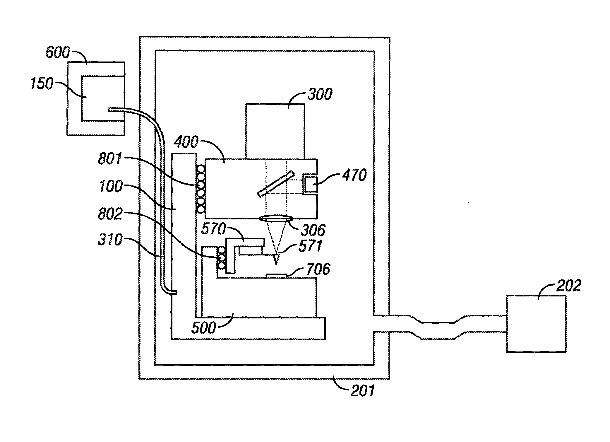
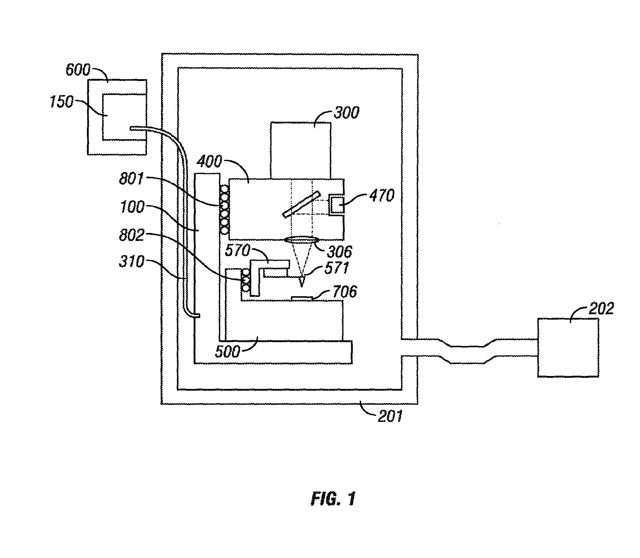
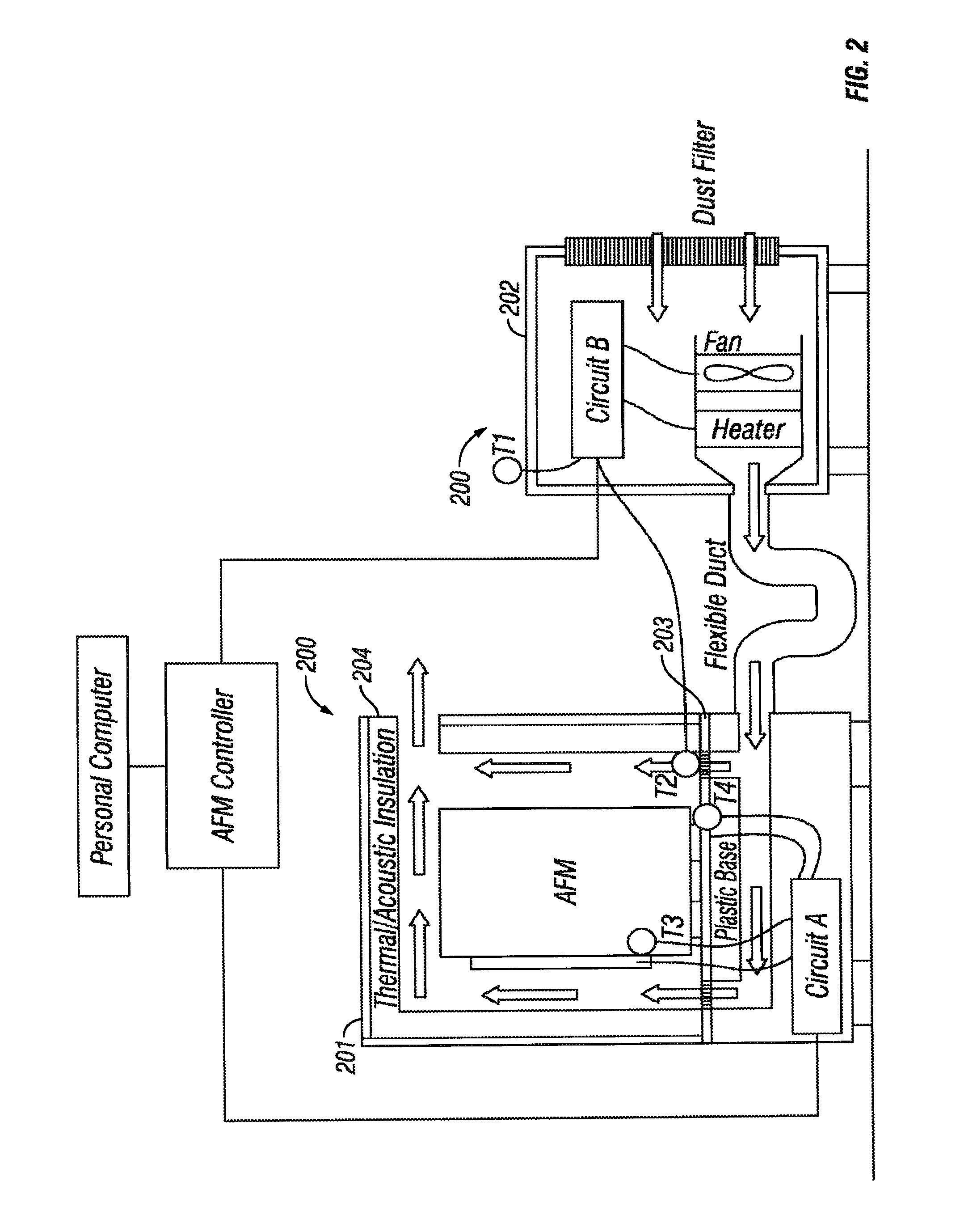
[0033]FIG. 1 shows an overall block diagram of an embodiment of the present invention, a modular AFM. The block diagram shows different subassemblies that each carry out different functions. The Chassis 100 is the foundation on which the modules of the modular AFM are supported. The View module 300 provides the optics for viewing the sample and the probe. The Head module 400 includes the components for the optical lever arrangement and for steering and focusing those components. The Scanner module 500 includes the XYZ translation stage that actuates the sample in those dimensions and the engage mechanism. The Isolation module 200 encloses the Chassis 100 and provides acoustic and / or thermal isolation for the modular AFM. The Electronics module 600, together with the controller for the modular AFM, provide the electronics for acquiring and processing images and controlling the other functions of the modular AFM. The Electronics module 600 is mounted adjacent the other modules of the ...


PUM


Abstract

A modular AFM / SPM which provides faster measurements, in part through the use of smaller probes, of smaller forces and movements, free of noise artifacts, that the old generations of these devices have increasingly been unable to provide. The modular AFM / SPM includes a chassis, the foundation on which the modules of the instrument are supported; a view module providing the optics for viewing the sample and the probe; a head module providing the components for the optical lever arrangement and for steering and focusing those components; a scanner module providing the XYZ translation stage that actuates the sample in those dimensions and the engage mechanism; a isolation module that encloses the chassis and provides acoustic and / or thermal isolation for the instrument and an electronics module which, together with the separate controller, provide the electronics for acquiring and processing images and controlling the other functions of the instrument. All these modules and many of their subassemblies are replaceable and potentially upgradeable. This allows updating to new technology as it becomes available.

Description

REFERENCES CITEDU.S. Patent Documents[0001]U.S. Pat. No. 5,825,020 10 / 1998 Hansma, et al.[0002]U.S. Pat. No. 6,871,527 3 / 2005 Hansma, et al.OTHER PUBLICATIONS[0003]Eur Pat App 90107769 4 / 1989 Okada, et al.BACKGROUND OF THE INVENTION[0004]Scanning probe devices such as the atomic force microscope (AFM) can be used to obtain an image or other information indicative of the features of a wide range of materials with molecular and even atomic level resolution. In addition, AFMs are capable of measuring forces accurately at the piconewton to micronewton range, in a measurement mode known as a force-distance curve or force curve. As the demand for resolution has increased, requiring the measurement of decreasingly smaller forces and movements free of noise artifacts, the old generations of these devices are made obsolete. A demand for faster results, requiring decreasingly smaller cantilevers, only reinforces this obsolescence. The preferable approach is a new device that addresses the cen...

Claims


Application Information

Patent Timeline
Patent Type & Authority Patents(United States)
IPC IPC(8): G01Q30/10G01Q30/08G01Q60/38
CPCB82Y35/00G01Q10/02G01Q30/18G01Q20/02G01Q10/04
Inventor PROKSCH, ROGERVIANI, MARIOCLEVELAND, JASONRUTGERS, MAARTENKLONOWSKI, MATTHEWWALTERS, DARENHODGSON, JAMESHENSEL, JONATHANCOSTALES, PAULGANNEPALLI, ANIL
Owner OXFORD INSTR ASYLUM RES INC
Learn More