Loop forming and loosening mechanism and sinkers thereof for circular knitting machines

a technology of loop forming and loosening mechanism and circular knitting machine, which is applied in the direction of knitting, weft knitting, textiles and papermaking, etc., can solve the problems of difficulty in manufacturing, difficulty in and inability to manufacture needle cylinders, so as to improve quality and production yield of needle cylinders, reduce labor and material costs, and simplify the effect of needle cylinder fabrication

Inactive Publication Date: 2013-02-12
PAI LUNG MACHINERY MILL CO LTD
View PDF8 Cites 2 Cited by
  • Summary
  • Abstract
  • Description
  • Claims
  • Application Information

AI Technical Summary

Benefits of technology

[0006]The primary object of the present invention is to solve the aforesaid disadvantages by providing a loop forming and loosening mechanism for circular knitting machines to simplify fabrication of needle cylinder, reduce labor and material costs, improve quality and production yield of the needle cylinder, reduce abrasion of sinkers, enhance performance of the mechanism and increase lifespan of the sinkers.

Problems solved by technology

1. Each sinker 3a of the conventional loop forming and loosening mechanism 1a of the circular knitting machine has a correcting segment 34, hence the needle cylinder 4a has to form a plurality of correcting troughs 41 thereon during fabrication. This creates structural complexity of the needle cylinder 4a and makes fabrication more difficult. The quality and production yield of the needle cylinder 4a decrease, and material and labor costs increase.
2. When the sinker 3a moves reciprocally and horizontally the correcting segment 34 also moves reciprocally and constantly in the correcting trough 41 that produces a lot of contact friction. This generates high temperature on the sinker 3a during long time of operation, and significant wearing or deformation could happen that shortens the lifespan of the sinker 3a. Moreover, loading of electric power also increases and performance of the loop forming and loosening mechanism 1a suffers. The entire knitting environment also could be contaminated.

Method used


Image

  • Loop forming and loosening mechanism and sinkers thereof for circular knitting machines
  • Loop forming and loosening mechanism and sinkers thereof for circular knitting machines
  • Loop forming and loosening mechanism and sinkers thereof for circular knitting machines

Examples


Embodiment Construction

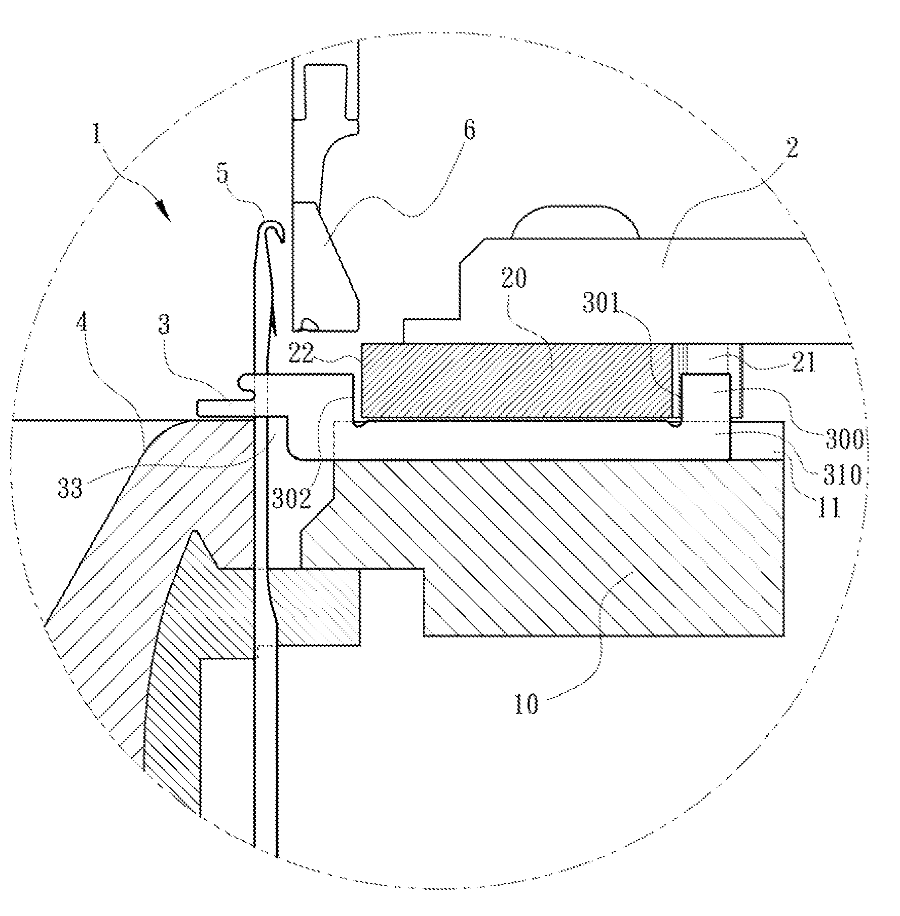
[0024]Please refer to FIGS. 3 through 5, the present invention aims to provide a loop forming and loosening mechanism 1 for circular knitting machines. It includes a needle cylinder 4 to hold a plurality of needles 5 located vertically, a sinker tray 10 located at the circumference of the needle cylinder 4 with a plurality of horizontal sinker grooves 11 formed thereon each holding a sinker 3, and a cam holder 2 located above the sinkers 3 to hold a plurality of cams 20. Each cam 20 has a first guide track 21 and a second guide track 22 to drive the sinkers 3 to move horizontally. The present invention further provides features as follows: each sinker 3 includes a sliding segment 31 with a sliding portion 310 slidably located in one sinker groove 11, a loop forming and loosening ancillary segment 32 extended upwards from one side of the sliding portion 310 and then extended outwards and including a yarn pressing notch 320 indented horizontally to aid each needle 5 to form or loosen ...


PUM


Abstract

A sinker includes a sliding segment with a sliding portion slidably located in a sinker groove, a loop forming and loosening ancillary segment extended upwards from one side of the sliding portion and then extended outwards, a passive segment located above the sliding segment and driven by a cam, and an indented abrasion-reducing space located at a lateral side of the sliding portion and below the loop forming and loosening ancillary segment. Through the abrasion-reducing space, the loop forming and loosening ancillary segment can move directly and horizontally above a needle cylinder. The loop forming and loosening mechanism for circular knitting machines of the invention can simplify fabrication of the needle cylinder, reduce labor and material costs, improve quality and production yield of the needle cylinder, and also reduce abrasion of the sinker, thus can improve performance of the mechanism and enhance lifespan of the sinker.

Description

FIELD OF THE INVENTION[0001]The present invention relates to a mechanism and elements of circular knitting machines and particularly to a mechanism and sinkers thereof for a circular knitting machine to aid knitting needles in loop forming and loosening.BACKGROUND OF THE INVENTION[0002]A conventional loop forming and loosening mechanism 1a of a circular knitting machine, referring to FIGS. 1 and 2, includes a needle cylinder 4a to hold a plurality of needles 5a located vertically, a plurality of correcting troughs 41 above the needle cylinder 4a, a sinker tray 10a located at the circumference of the needle cylinder 4a with a plurality of horizontal sinker grooves 11a formed thereon each holding a sinker 3a, and a cam holder 2a located above the sinkers 3a to hold a plurality of cams 20a. The cams 20a aim to drive the sinkers 3a to move reciprocally and horizontally. Each sinker 3a includes a sliding segment 31a with a sliding portion 310a slidably located in one sinker groove 11a, a...

Claims


Application Information

Patent Timeline
Patent Type & Authority Patents(United States)
IPC IPC(8): D04B27/04
CPCD04B15/06D04B15/14
Inventor PAI, TIEH-HSIUNG
Owner PAI LUNG MACHINERY MILL CO LTD
Why Eureka
Try Eureka