Railgun with steel enclosed gun bore

a railgun and steel technology, applied in the field of railguns, can solve the problems of mutual repulsive force, inability to properly confine the high voltage rails within, and the gun bore is too heavy for practical us

Inactive Publication Date: 2013-02-12
PROULX GEORGE ARTHUR
View PDF21 Cites 12 Cited by
  • Summary
  • Abstract
  • Description
  • Claims
  • Application Information

AI Technical Summary

Benefits of technology

[0018]An electromagnetic railgun (10) comprising at least two elongated high voltage rails (11), a sliding armature (50) making electrical contact with each high voltage rail (11), at least two elongated metal support beams (14) adapted to provide mechanical strength to the railgun (10), said support beams (14) being substantially parallel to the high voltage rails (11), and a plurality of electrically conductive support plates (30) aligned circumferentially around the support beams (14) and along the length of the railgun (10), said support plates (30) adapted to provide additional mechanical strength to the railgun (10); wherein the support plates (30) are electrically isolated from each other and from the support beams (14).

Problems solved by technology

One problem that has remained unsolved for many years has been the inability to properly confine the high voltage rails within the gun bore at power levels of interest and for useful lifetimes. During armature launch, the current in each of the rails results in a mutually repulsive force.
However, in that case, the intervening volume would need to be filled with dielectric material, and the resulting gun would be too heavy for practical use.
As a result of this, the conversion efficiency of electrical energy to kinetic energy of the projectile would be very poor.
For very powerful railguns operating at mega-ampere levels, however, some amount of rail containment using metals is required, as the tensile strength of dielectric materials is too low to adequately constrain the rails by themselves.
However, and because the remainder of the railgun containment is constructed of dielectrics, there remains a serious problem of gun barrel droop.
The current-carrying high voltage rails must be made of a highly conductive material such as copper, or more commonly a copper alloy, and cannot contribute to railgun stiffness along the bore axis, because copper is a relatively soft and ductile metal.
Dielectric materials generally have insufficient tensile strength to produce railgun stiffness for a long gun bore.
As a consequence of this and to achieve a desired exit velocity for the projectile, the acceleration rate is correspondingly increased, which severely burdens other railgun systems, such as the electrical power source and the rails, given the commensurately higher rail currents that are now required.
In addition, in pulsed mode of railgun powering, there remains considerable uncertainty that the remaining dielectric materials will have the reliability and lifetime to provide a practical solution, especially given that these materials are used in tension.
However, these guide rails are embedded into the surrounding dielectric material.
Dielectric material is relatively weak mechanically and is limited in its ability to support these mechanical guide rails for a large number of launches without degradation of the underlying dielectric material.

Method used


Image

  • Railgun with steel enclosed gun bore
  • Railgun with steel enclosed gun bore
  • Railgun with steel enclosed gun bore

Examples


Embodiment Construction

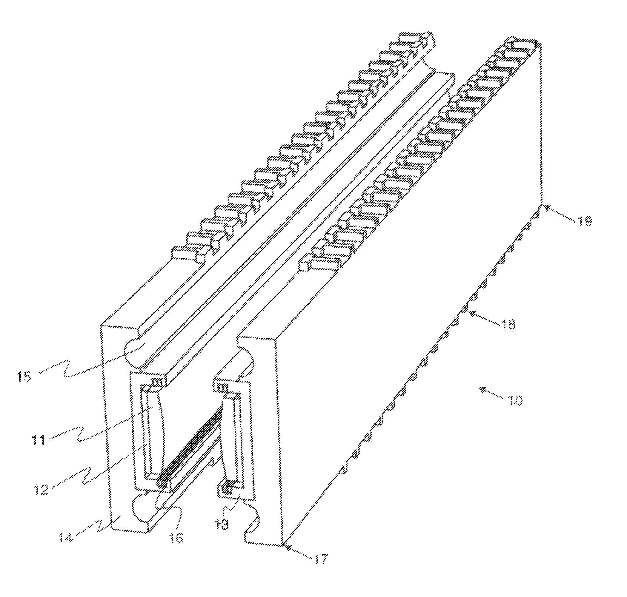
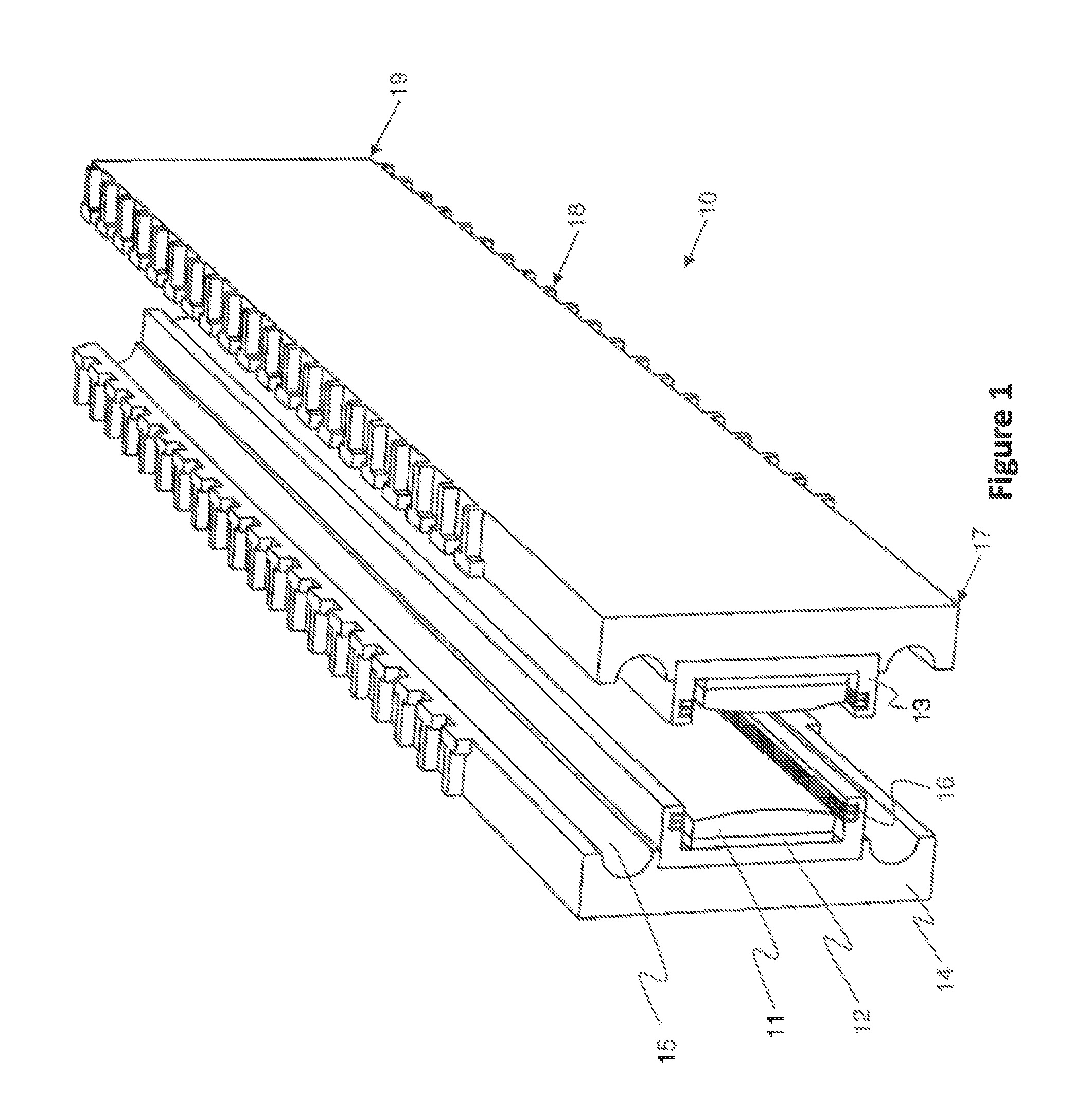
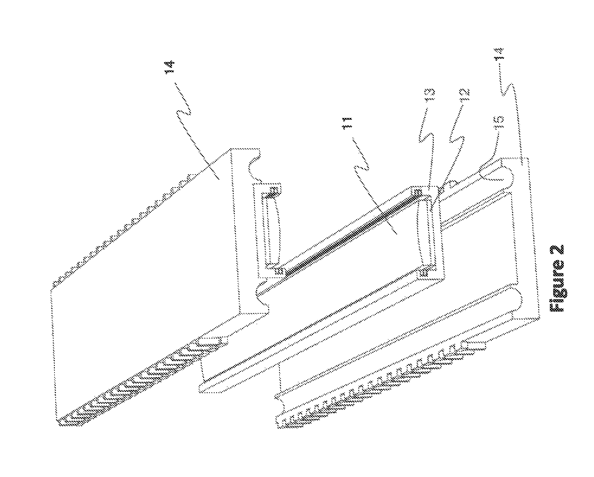
[0030]The railgun 10 comprises a breech 17, a muzzle 19, and a bore 18. An armature 50 propels a projectile (not illustrated) along the gun bore 18 between high voltage rails 11. There is a support beam 14 associated with each high voltage rail 11. A two-rail 11 system is illustrated herein, but this invention is not limited to two-rail 11 systems; any discrete number of rails 11 greater than or equal to two can be used. Each support beam 14 is proximate the back (outside) of each high voltage rail 11, as shown in FIG. 1.

[0031]Each high voltage rail 11 is electrically isolated from its respective support beam 14 by being mounted onto an electrical insulator 12. Preferably, the electrical insulator 12 is made of a ceramic material. Insulator 12 can generally be any electrical insulator operable up to approximately 30 kV that is also mechanically robust, such as G10. Each electrical insulator 12 can be directly attached to a corresponding support beam 14. Preferably, however, each hig...


PUM


Abstract

An electromagnetic railgun (10) comprising at least two elongated high voltage rails (11), a sliding armature (50) making electrical contact with each high voltage rail (11), at least two elongated metal support beams (14) adapted to provide mechanical strength to the railgun (10), said support beams (14) being substantially parallel to the high voltage rails (11), and a plurality of metal support plates (30) aligned circumferentially around the support beams (14) and along the length of the railgun (10), said support plates (30) adapted to provide additional mechanical strength to the railgun (10); wherein the support plates (30) are electrically isolated from each other and from the support beams (14).

Description

RELATED PATENT APPLICATIONS[0001]This patent application is a continuation-in-part of commonly-owned U.S. patent application Ser. No. 12 / 537,482 filed Aug. 7, 2009, entitled “Railgun System”; and additionally claims the benefit of the following four commonly-owned U.S. provisional patent applications: U.S. patent application 61 / 283,868 filed Dec. 10, 2009, entitled “Railgun with External Rails to the Gun Bore”, U.S. patent application 61 / 339,328 filed Mar. 2, 2010, entitled “Railgun with Inductive and Direct Drive Options”, U.S. patent application 61 / 342,163, filed Apr. 8, 2010, entitled “Railgun with Rails External to the Gun Bore—Part B”, and U.S. patent application 61 / 404,214 filed Sep. 28, 2010, entitled “Railgun with Steel Encased Bore”, all five of which patent applications are hereby incorporated by reference in their entireties into the present patent application.TECHNICAL FIELD[0002]This patent application pertains generally to the field of electromagnetic launchers, and sp...

Claims


Application Information

Patent Timeline
Patent Type & Authority Patents(United States)
IPC IPC(8): F41F1/00
CPCF42B6/00F41B6/006
Inventor PROULX, GEORGE ARTHUR
Owner PROULX GEORGE ARTHUR
Why Eureka
Try Eureka