Perturbed square ring slot antenna with reconfigurable polarization

a square ring slot, perturbed technology, applied in slot antennas, antennas, basic electric elements, etc., can solve the problems of introducing an extra layer of complexity, no operation in lp, limited design, etc., to achieve wide cp bandwidth, low cost, and cost-effective

Active Publication Date: 2013-02-12
VIRGINIA TECH INTPROP INC +1
View PDF9 Cites 32 Cited by
  • Summary
  • Abstract
  • Description
  • Claims
  • Application Information

AI Technical Summary

Benefits of technology

[0012]The invention is directed to a perturbed slot with reconfigurable polarization that allows operation in LHCP, RHCP, or LP. This antenna topology is well-suited for wireless communications applications requiring polarization diversity. This design is realizable using cost effective printed circuit board technology making it an attractive design for low cost personal communications devices. Unlike previous ring slots with switchable perturbations that can only switch between two (2) polarization states, the perturbed square-ring slot antenna of the invention can be switched between RHCP, LHCP, or linear polarization (LP) by biasing a series of PIN diode switches, mak...

Problems solved by technology

This technique has the drawbacks of requiring two feed lines as well as a hybrid network of some kind to provide the necessary phase shift.
Yang describes a microstrip antenna with polarization diversi...

Method used


Image

  • Perturbed square ring slot antenna with reconfigurable polarization
  • Perturbed square ring slot antenna with reconfigurable polarization
  • Perturbed square ring slot antenna with reconfigurable polarization

Examples


Embodiment Construction

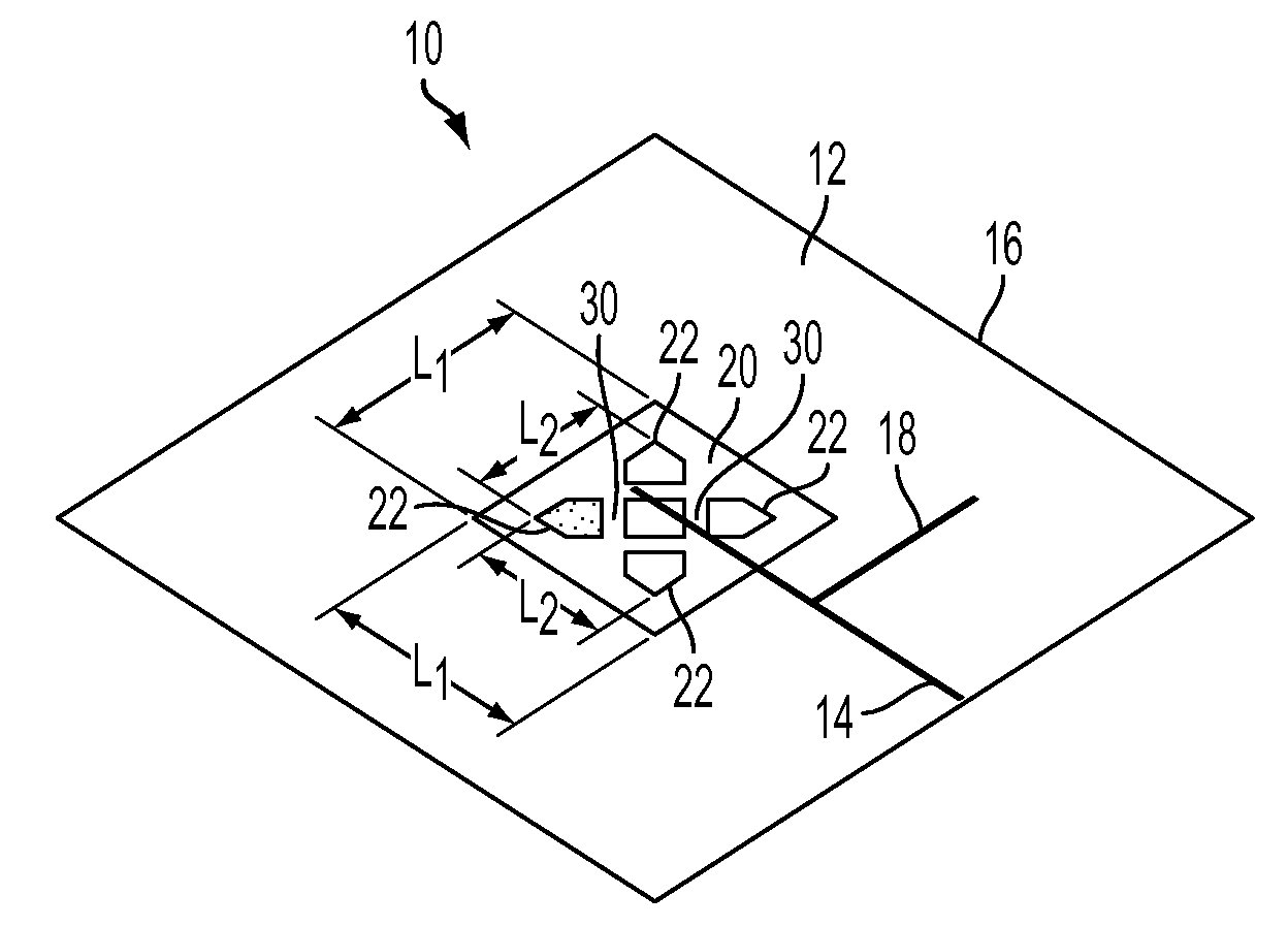
[0026]The reconfigurable square-ring slot antenna 10 according to the invention is illustrated in FIG. 4. FIG. 4A shows the ground plane 12 and the feeding microstrip line 14 which are printed on opposite sides of a microwave substrate 16. The reconfigurable antenna designed by the inventor utilized a Rogers 4350 microwave substrate having a dielectric constant of 3.48. However, this design is not limited to that substrate. The microstrip line 14 contains a shunt stub 18 for matching. The stub 18 was added because the optimal axial ratio (AR) occurred outside of the optimal return loss bandwidth. The perturbed slot 20 is separated into five conducting patches 22 as seen in FIG. 4B. PIN diode switches 24 are placed between the center conducting patch (C1) and the outer four conducting patches (C2, C3, C4, and C5). Referring also now to FIG. 9, these switches 24 consist of a PIN diode 26 in series with a large capacitor 28 which is used to maintain continuity between the RF grounded c...


PUM


Abstract

A reconfigurable polarization antenna includes a microwave dielectric substrate having a ground plane that has a centrally located slot with five conducting patches, four of which form an evenly spaced apart perimeter group with a gap between each and the fifth, centrally positioned conducting patch. A conducting pad is positioned in each gap and is connected via a switch to the ground plane. A microstrip feed line including a short stub is positioned on the opposite side of the substrate and electromagnetically coupled to the slot. The polarization of the antenna is reconfigured by a selection of an on or off state of each of said switches.

Description

CROSS-REFERENCE TO RELATED APPLICATIONS[0001]This Application claims the benefit of U.S. Provisional Application 61 / 060,289 filed on Jun. 10, 2008.BACKGROUND OF THE INVENTION[0002]The invention is directed to an antenna with reconfigurable polarization, and more particularly, to an antenna having a perturbed square ring slot configuration for operating in multiple polarizations.[0003]Circular polarized (CP) antennas are popular choices in mobile wireless communications applications owing to their ability to allow flexible orientation between the transmitter and receiver antennas and to reduce multipath effects that can lead to signal fading, e.g. as described in S. H. Hsu and K. Chang, “A Novel Reconfigurable Microstrip Antenna with Switchable Circular Polarization”, IEEE Antennas and Wireless Propagation Let., Vol. 6, 2007, pp. 160-162; Y. J. Sung, T. U. Jang, and Y. S. Kim, “A Reconfigurable Microstrip Antenna for Switchable Polarization”, IEEE Microwave & Wireless Components Let....

Claims


Application Information

Patent Timeline
IPC IPC(8): H01Q13/10
CPCH01Q21/245H01Q19/005
Inventor DORSEY, W MARKZAGHLOUL, AMIR IPARENT, MARK G
Owner VIRGINIA TECH INTPROP INC
Why Eureka
Try Eureka