Snow making apparatus and method

a technology of snow making apparatus and snowmaking machine, which is applied in the direction of lighting and heating apparatus, way cleaning, construction, etc., can solve the problems of low energy, limited snow throwing power, and parts which are not easily removable and replaceable, so as to reduce the profile, prevent ice formation, and easy and quick attachment and removal

Active Publication Date: 2013-02-19
RATNIK IND
View PDF17 Cites 1 Cited by
  • Summary
  • Abstract
  • Description
  • Claims
  • Application Information

AI Technical Summary

Benefits of technology

[0003]The present invention addresses the above need by providing in a low energy consumption snow making gun and method. In one aspect, the snow gun includes components having low profiles and spacing which discourages ice formation thereon. In another aspect, the snow gun includes improved valve configuration and operation of the individual stages. In yet another aspect, the snow gun water outlets are configured, sized, spaced and angled in a manner creating individualized water droplet streams which do not interfere with each other until they have traveled a distance from the snow gun. This allows the individual water droplet streams to maintain maximum momentum before they converge and form a single plume of snow propelled in one controlled direction. Each water outlet may be provided on a single nozzle although in a preferred embodiment, at least two water outlets are provided on a single nozzle. The size of the water outlets are small and generate a narrow angled V-shaped plume compared to typical prior art water outlets and the flow capacity of one pair of water outlets in the present invention may total a single larger water outlet of the prior art. Through proper spacing and directional orientation of the smaller water outlets, the present invention achieves improved snow throwing power than is attainable with prior art low energy snow guns.
[0005]The water nozzles may be made from a durable material such as stainless steel and include one or more small diameter outlet apertures which may be smaller on the pressure side of the nozzle opposite the exiting stream. In a preferred embodiment, a single nozzle includes at first and second water outlets arranged one above the other although it is understood that each water outlet may be formed on an individual nozzle. Also, although the invention is described and shown herein as having two outlets on a single nozzle head, more than two water outlets may be provided on a single nozzle head or stage. In a preferred embodiment, the snow gun includes at least one, but more preferably three individually operated snow making stages with at least two water outlets provided on each stage. Each vertically spaced pair of water outlets on each stage are oriented to diverge their respective water streams to prevent the stream from converging prematurely close to the gun. In the preferred embodiment, a second pair of water outlets is provided on each stage in annularly spaced relation to the first pair of water outlets for a total of four water outlets per stage. The first and second pairs of water outlets on each stage are oriented in a horizontally diverging manner, again to prevent premature convergence of the individual streams.
[0007]A nucleator block is provided directly below a column of water outlets on the one or more stages and includes a water and air outlet for to atomize and project a plume of fine mist into the water droplet streams to form snow. The nucleator block may be formed of any suitable material such as brass or stainless steel which retains heat from the water flow and is low in profile which discourages ice formation thereon. The nucleator block is configured for easy and quick attachment and removal from the snow gun, e.g., by pair of screws extending through the block.

Problems solved by technology

Prior art low energy guns have many problems including, for example, freezing of the components which have geometries allowing ice to collect on and in the gun, parts which are not easily removable and replaceable for servicing, limited snow throwing power due to a lack of controlled directionality and interference between the streams generated from the various nozzles, and low snow output as related to power consumption.
This causes the streams to immediately lose momentum and directionality.

Method used


Image

  • Snow making apparatus and method
  • Snow making apparatus and method
  • Snow making apparatus and method

Examples


Embodiment Construction

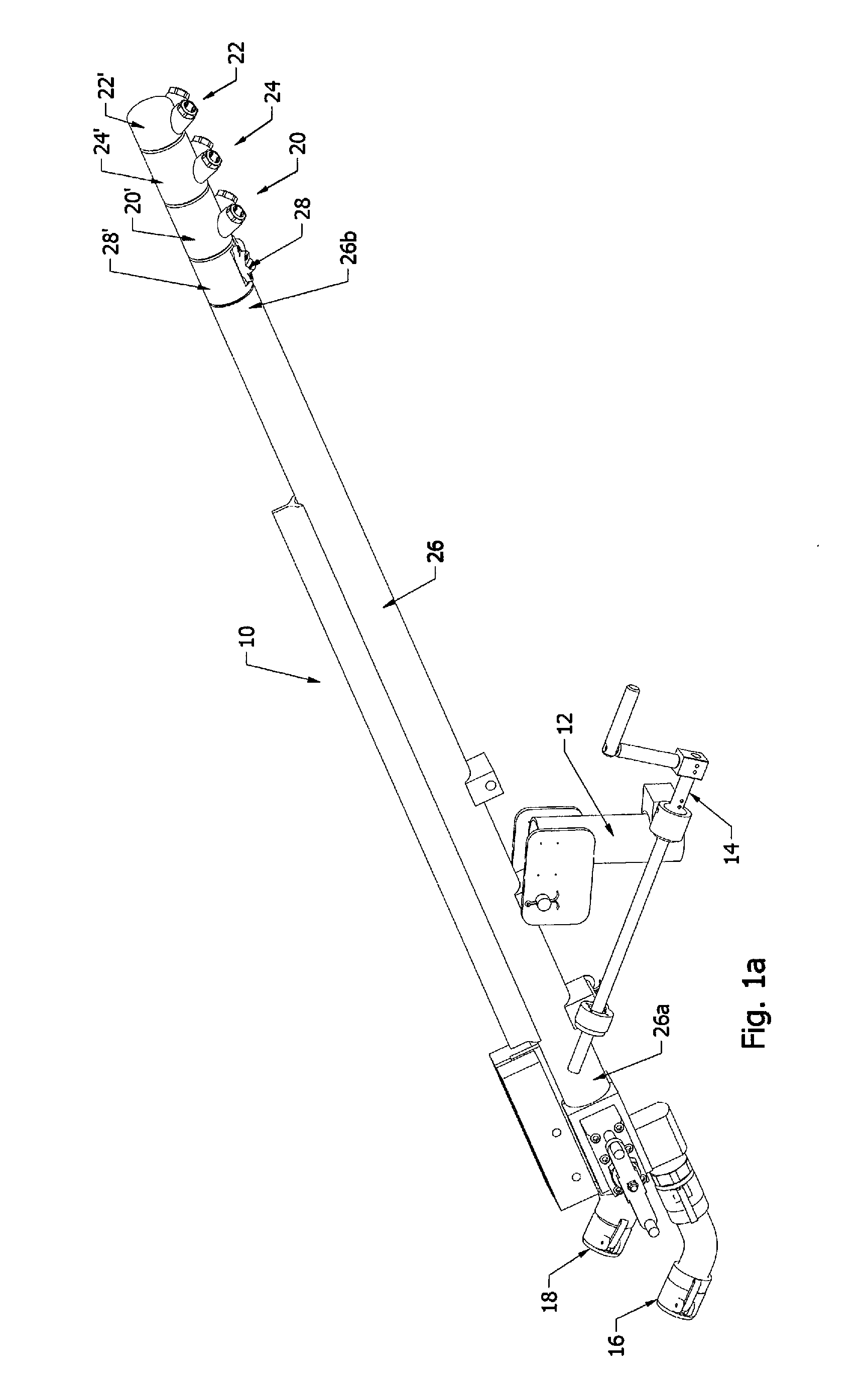
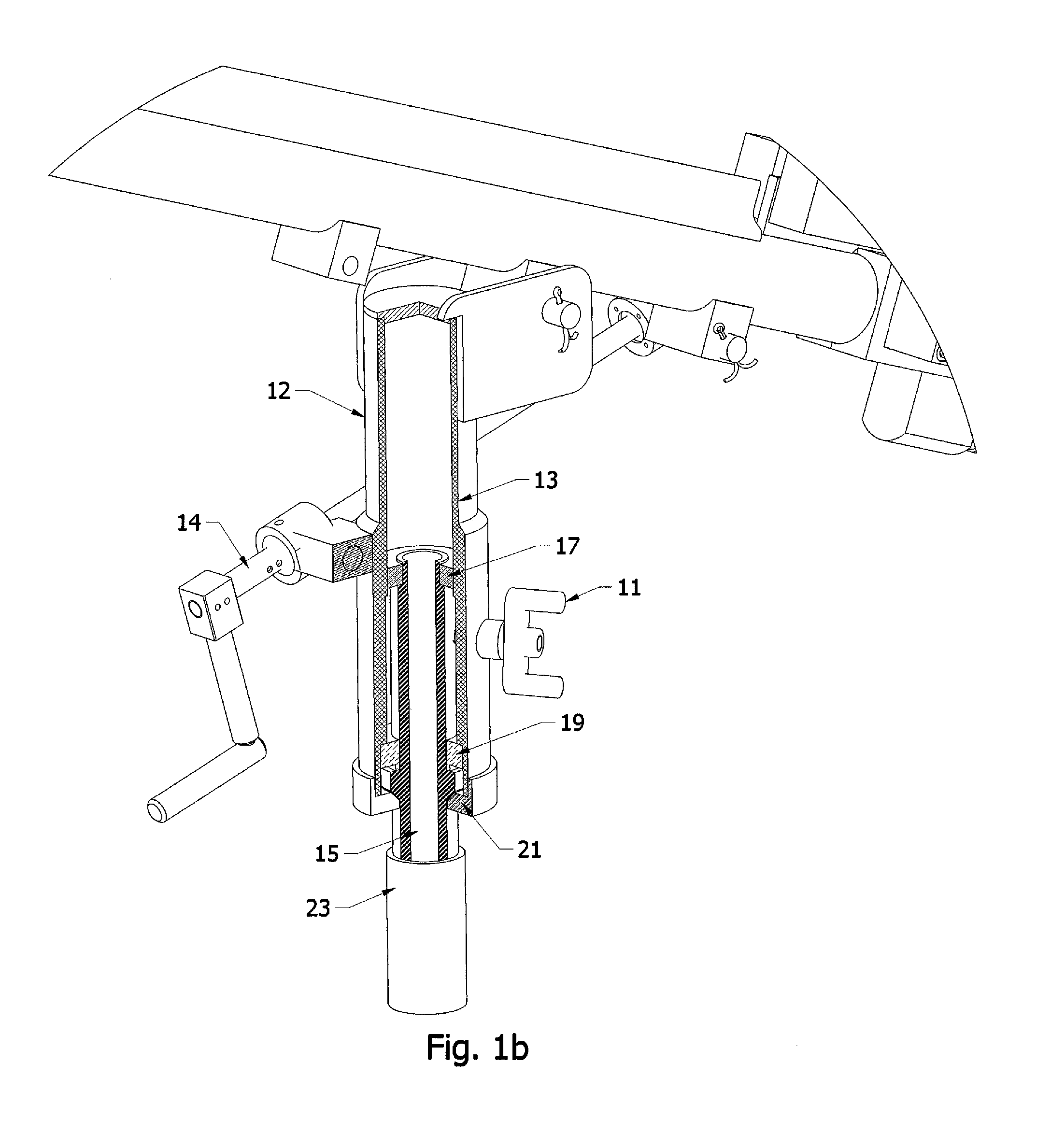
[0027]Referring to the Drawing, there is seen in FIG. 1a a snow making gun designated generally by the reference numeral 10. Snow gun 10 includes a mounting stand 12 for pivotally mounting snow gun 10 to an appropriate ground post or sled at the ski slope (not shown). The height and angle of snow gun 10 may be adjusted via handle and jack screw assembly 14. For a snow gun that is not intended to pivot on a stand, a fixed stand 12 may be provided. For a snow gun that is meant to pivot, as seen in FIG. 1b, jack screw assembly 14 may be mounted to an outer casing 13 which may pivot about an inner shaft 15 via ball bearing 17 and thrust bearing 19. A locking cap 21 may be provided to removably secure inner shaft 15 into a tower stand 23 which itself may be in fixed position at the ski slope or mounted to a sled that may be transported to other locations. In one embodiment of the invention, an optional sail 25 seen in FIGS. 3a and 3b is provided for attaching to tower stand 23. Sail 25 m...


PUM


Abstract

A low energy snow making gun having at least one but preferably three operational stages each having at least one pair of small aperture water outlets which are oriented at a divergent angle to generate a respective pair of narrow angled water droplet streams which do not interfere with each other until they have reached a distance from the gun. A second pair of water outlets may be provided on each stage with each pair on each stage oriented at a divergent angle to maintain singularity of the streams over a distance thereby increasing the throwing power of the gun.

Description

BACKGROUND OF THE INVENTION[0001]The present invention generally relates to methods and apparatus for making snow, and more particularly relates to a low energy snow making gun useful for making snow at ski resorts.[0002]Snow making guns are known for making snow along ski slopes to maintain the slopes at their optimum condition for skiers. Snow guns operate by propelling water droplets into the air which collide with a plume generated by compressed air and atomized water whereupon the droplets form snow flakes that fall onto the slopes. Smaller snow guns which consume less energy than the large snow guns are more desirable as energy costs continue to rise. Prior art low energy guns have many problems including, for example, freezing of the components which have geometries allowing ice to collect on and in the gun, parts which are not easily removable and replaceable for servicing, limited snow throwing power due to a lack of controlled directionality and interference between the st...

Claims


Application Information

Patent Timeline
Patent Type & Authority Patents(United States)
IPC IPC(8): F25C3/04
CPCF25C3/04F25C2303/0481
Inventor RATNIK, HELDUR R.WANG, TIMOTHY C.CARSON, MATTHEW A.
Owner RATNIK IND
Why Eureka
Try Eureka