
Method of controlling a hybrid helicopter in yaw, and a hybrid helicopter provided with a yaw control device suitable for implementing said method

a technology of yaw control device and hybrid helicopter, which is applied in the direction of propellers, automatic actuation, position/direction control, etc., can solve the problems of helicopter yawing violently, subjecting the helicopter to severe mechanical stress,

Inactive Publication Date: 2013-02-19
EUROCOPTER
View PDF29 Cites 24 Cited by
  • Summary
  • Abstract
  • Description
  • Claims
  • Application Information

AI Technical Summary

Benefits of technology

This patent is for a hybrid helicopter with yaw control means. The helicopter has two propellers, with different blades that can change their pitch to modify the helicopter's yaw angle. The control means uses an original order that is optimized based on the helicopter's thrust control to apply to both blades. The control means can vary the gain and correction term as a function of the thrust control to ensure pilotability and comfort. At high speeds, the yaw control means is reduced in its authority to minimize its action. The control means can also use non-linear relationships to achieve symmetrical yaw control authority and facilitate stable flight. Overall, this patent describes a method for optimizing yaw control in a hybrid helicopter to ensure safe and comfortable flight.

Problems solved by technology

Nevertheless, it is found that abusive use of the rudder bar can lead to a maneuver that subjects the helicopter to severe mechanical stress, or even to the hybrid helicopter yawing violently.

Method used


Image

  • Method of controlling a hybrid helicopter in yaw, and a hybrid helicopter provided with a yaw control device suitable for implementing said method
  • Method of controlling a hybrid helicopter in yaw, and a hybrid helicopter provided with a yaw control device suitable for implementing said method
  • Method of controlling a hybrid helicopter in yaw, and a hybrid helicopter provided with a yaw control device suitable for implementing said method

Examples


first embodiment

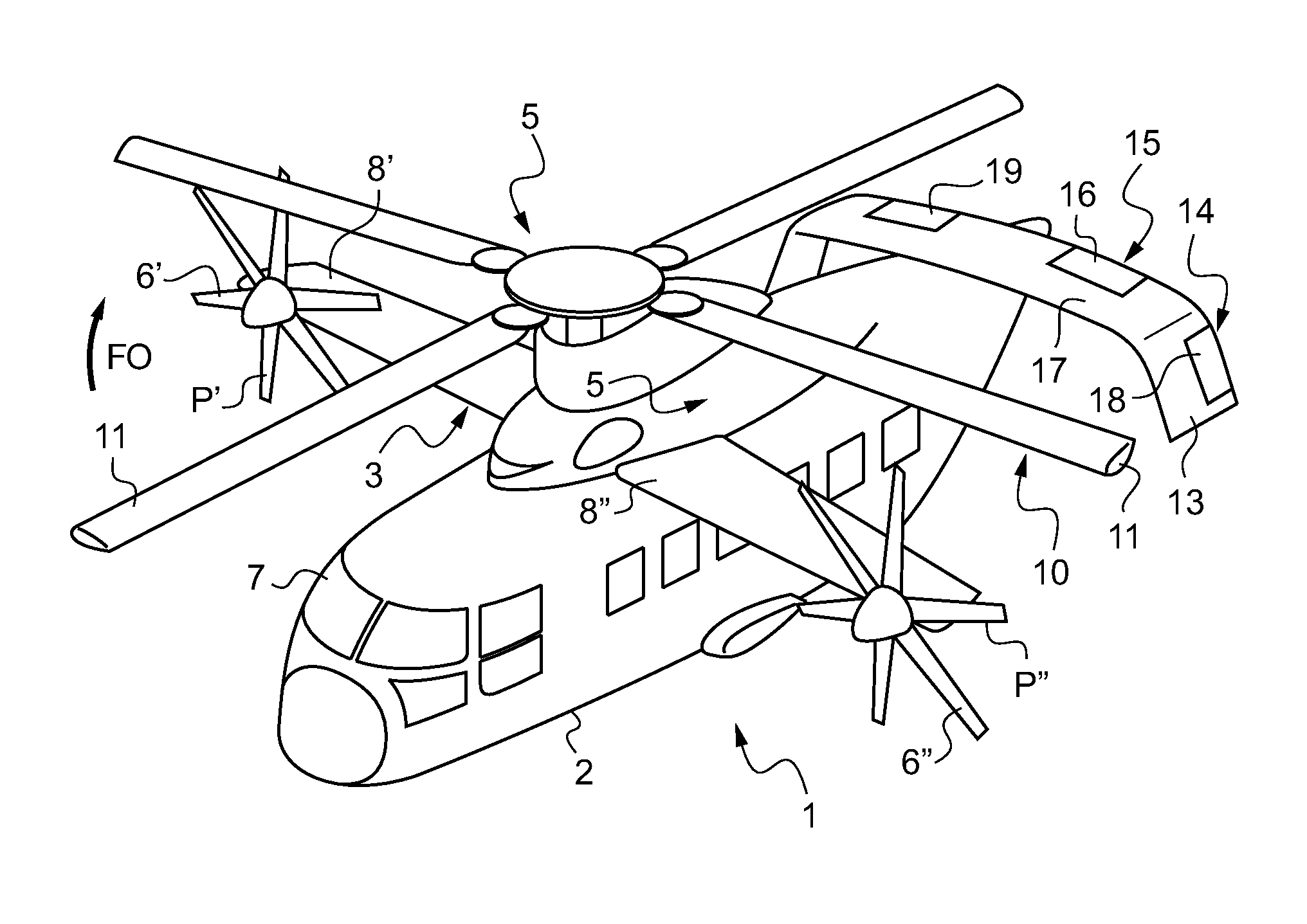
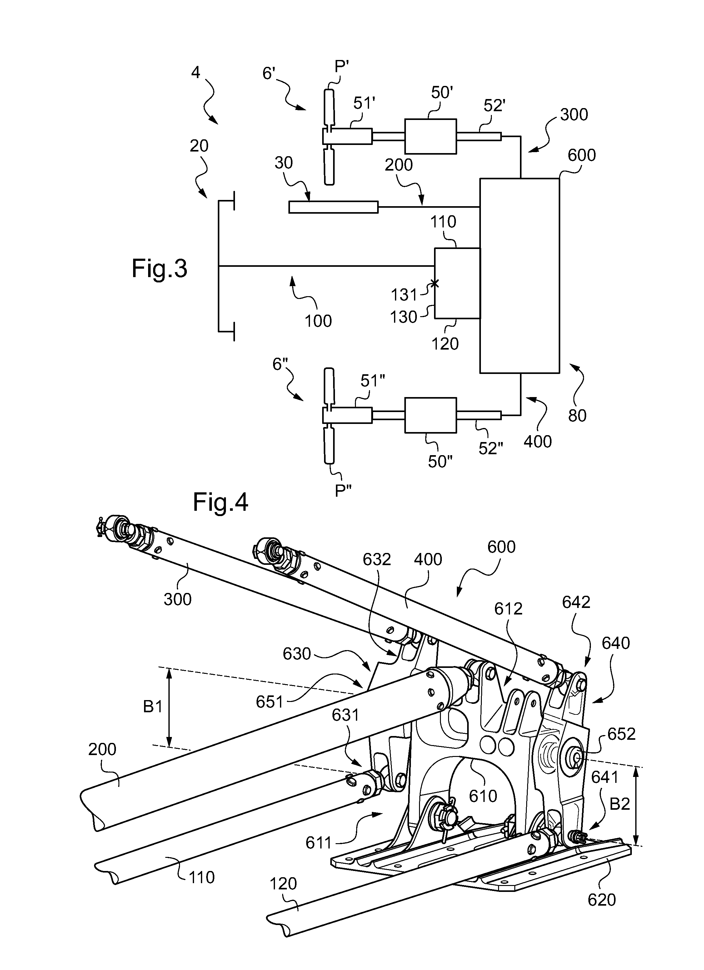
[0160]FIG. 3 shows the invention implementing the first variant of the method as explained above.

[0161]The yaw control device 4 comprises yaw control means 20, a rudder bar, connected by a first main linkage 100 to a combiner 80.

[0162]More precisely, the first main linkage 100 is hinged to an intermediate rocker 130 suitable for performing rocking motion about a pivot 131, said intermediate rocker being connected to a combiner by a left link 110 and a right link 120.

[0163]The combiner 80 is also connected to a first control rod 52′ of a first hydraulic valve 50′ by a first secondary linkage 300. As a function of the orders given by the pilot, the first control rod 52′ is moved so that the first hydraulic valve 50′ connects a first servo-control 51′ to the hydraulic circuit of the hybrid helicopter so as to modify the first pitch of the first blade P′ of the first propeller 6′.

[0164]Similarly, the combiner 80 is connected to a second control rod 52″ of a second hydraulic valve 50″ vi...

second embodiment

[0193]FIG. 6 shows a second embodiment implementing the above-described second variant.

[0194]The yaw control device 4 comprises yaw control means 20, a rudder bar, and a thrust control 30 connected to the combiner 80 respectively via first and second main linkages 100, 200.

[0195]Unlike the first embodiment, the combiner 80 is a simple conventional combiner 601 and not a combiner / coupler 600.

[0196]The combiner 80 then does not add a corrective term to the original order.

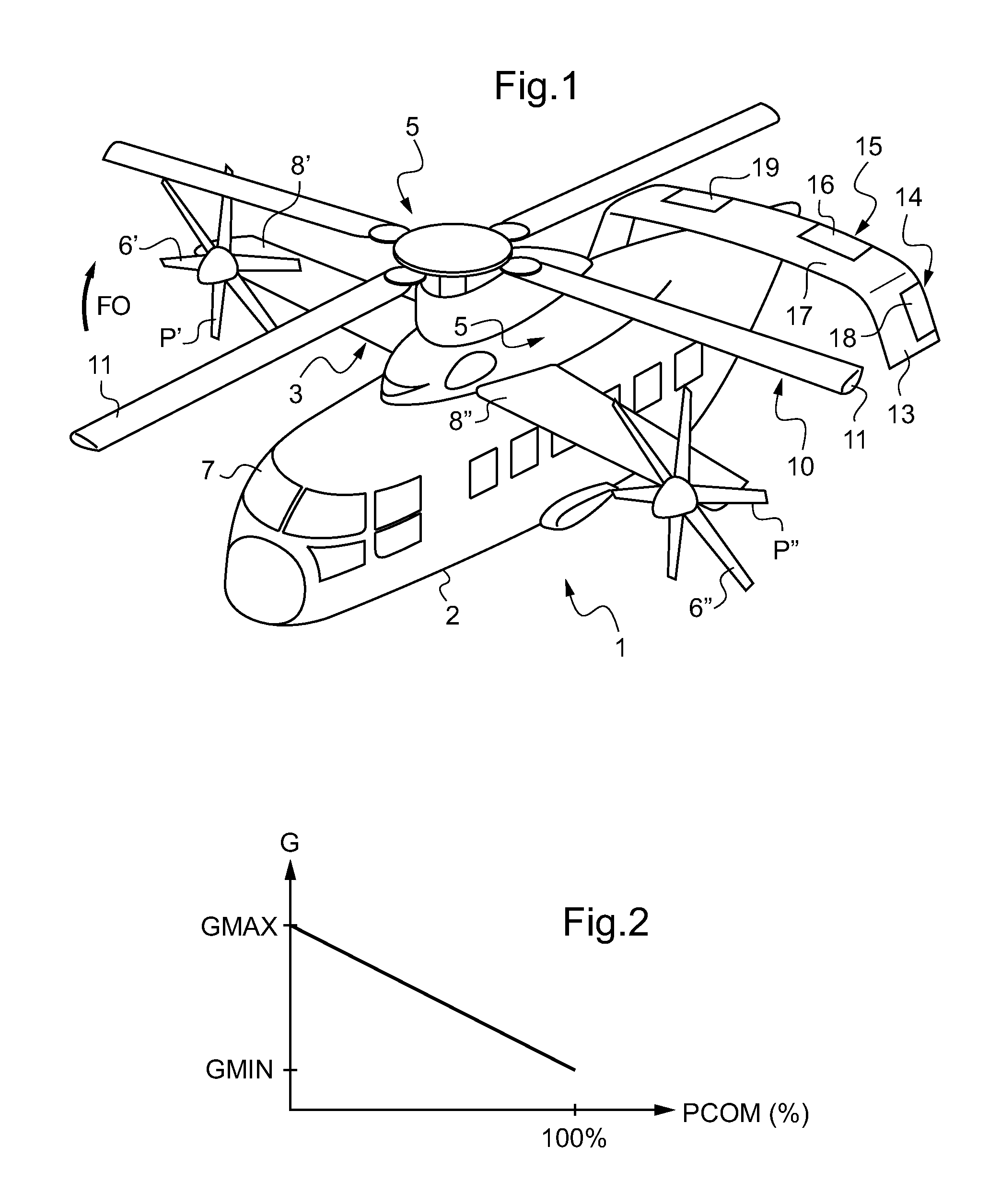
[0197]In the second embodiment, the adjustment means possess second optimization means not for correcting the original order given by a pilot via the yaw control means 20, but rather for modulating it by a gain G.

[0198]Thus, the adjustment means comprise a crank 90 arranged between an upstream first main linkage 101 hinged to the yaw control means 20 and a downstream first main linkage 102 hinged to the combiner 80.

[0199]More precisely, the crank 90 has an upstream radius 91 and a downstream radius 92 constrained to p...

third embodiment

[0206]FIG. 8 shows a third embodiment implementing the above-described second variant.

[0207]The yaw control device 4 includes yaw control means 20, a rudder bar, and thrust control means 30 connected to the combiner 80 respectively via first and second main linkages 100, 200.

[0208]Like the second embodiment, the combiner 80 is a simple conventional combiner 601 and not a combiner / coupler 600.

[0209]The adjustment means then possess third optimization means not for correcting the original order given by a pilot via the yaw control means 20, but rather for modulating it by a gain G.

[0210]Thus, the adjustment means comprise first and second adjustable elements 60, 70 arranged respectively on the first and second secondary linkages 300, 400.

[0211]More precisely, the first adjustable element 60, such as a first electrical actuator provided with an actuator body 62 and an actuator rod 63, is fastened firstly to a first upstream secondary linkage 301 connected to the combiner 80, and second...


PUM


Abstract

A method of controlling the yaw attitude of a hybrid helicopter including a fuselage and an additional lift surface provided with first and second half-wings extending from either side of the fuselage, each half-wing being provided with a respective first or second propeller. The hybrid helicopter has a thrust control suitable for modifying the first pitch of the first blades of the first propeller and the second pitch of the second blades of the second propeller by the same amount. The hybrid helicopter includes yaw control elements for generating an original order for modifying the yaw attitude of the hybrid helicopter by increasing the pitch of the blades of one propeller and decreasing the pitch of the blades of the other propeller, the original order is optimized as a function of the position of the thrust control to obtain an optimized yaw control order that is applied to the first and second blades.

Description

FIELD OF THE INVENTION[0001]The present invention relates to a method of controlling a hybrid helicopter in yaw, and to a hybrid helicopter provided with a yaw control device suitable for implementing said method.[0002]More particularly, the invention thus relates to a hybrid helicopter applying an advanced concept for a vertical takeoff and landing (VTOL) aircraft.[0003]This advanced hybrid helicopter combines, at reasonable cost, the effectiveness in vertical flight of a conventional helicopter with the high travel speed performance made possible by using propulsive propellers and installing modern turbine engines.BACKGROUND OF THE INVENTION[0004]In order to understand the object of the invention clearly, it is appropriate to recall the main types of flying machine corresponding to airplanes and to rotorcraft.[0005]The term “rotorcraft” is used to designate any aircraft in which lift is provided in full or in part by one or more propellers of substantially vertical axis and of lar...

Claims


Application Information

Patent Timeline
Patent Type & Authority Patents(United States)
IPC IPC(8): B64C27/54B64C27/82
CPCB64C27/22
Inventor GEMMATI, BERNARDQUEIRAS, NICOLASEGLIN, PAUL
Owner EUROCOPTER
Learn More