Eureka AIR delivers breakthrough ideas for toughest innovation challenges, trusted by R&D personnel around the world.

Multi-stage compressor

Active Publication Date: 2013-02-19
LEOBERSDORFER MASCHFAB
View PDF19 Cites 2 Cited by
  • Summary
  • Abstract
  • Description
  • Claims
  • Application Information

AI Technical Summary

Benefits of technology

The present invention is about creating a multi-stage compressor that has improved oscillation behavior compared to similar compressors. This is achieved by rotating the cylinders in the high-pressure region by 180°, which reduces the run of the pistons and lowers the overall oscillations of the compressor. The combination of a rotary compressor in the low-pressure region and the 180°-rotated cylinders results in a highly compact compressor that can achieve high compression of gas with low oscillations. This makes it ideal for use in both mobile and ship-mounted compressor plants. The mutual arrangement of the cylinders also results in a lower center of mass of the compressor, which further improves its stability. Different control means can be used for efficient control of the multi-stage compressor, allowing for both on-site and remote control.

Problems solved by technology

Yet, here, no internal compression of the gas to be sucked off takes place so that compared to a multi-stage high-pressure compression a possible heating of the gas to be compressed and / or a condensate accumulation is not to be considered.

Method used


Image

  • Multi-stage compressor
  • Multi-stage compressor
  • Multi-stage compressor

Examples


Embodiment Construction

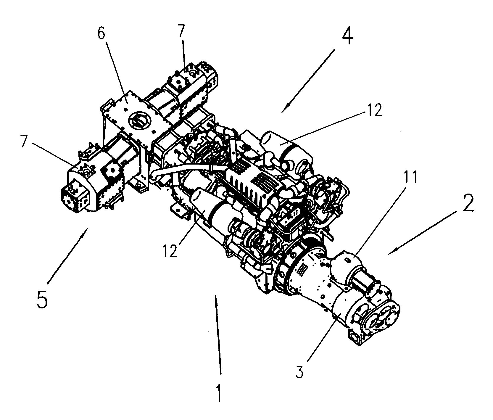
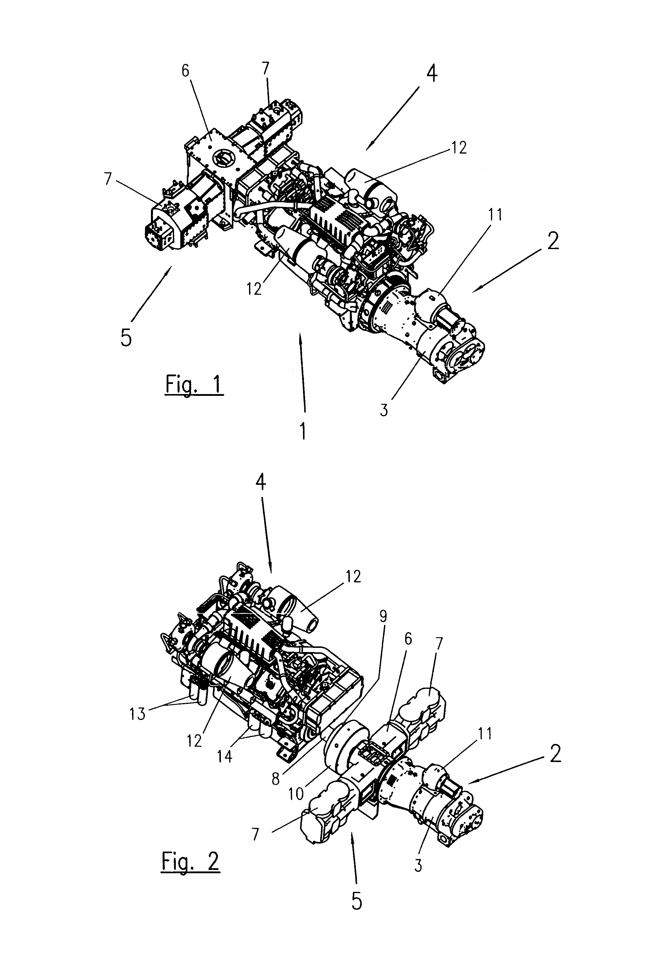
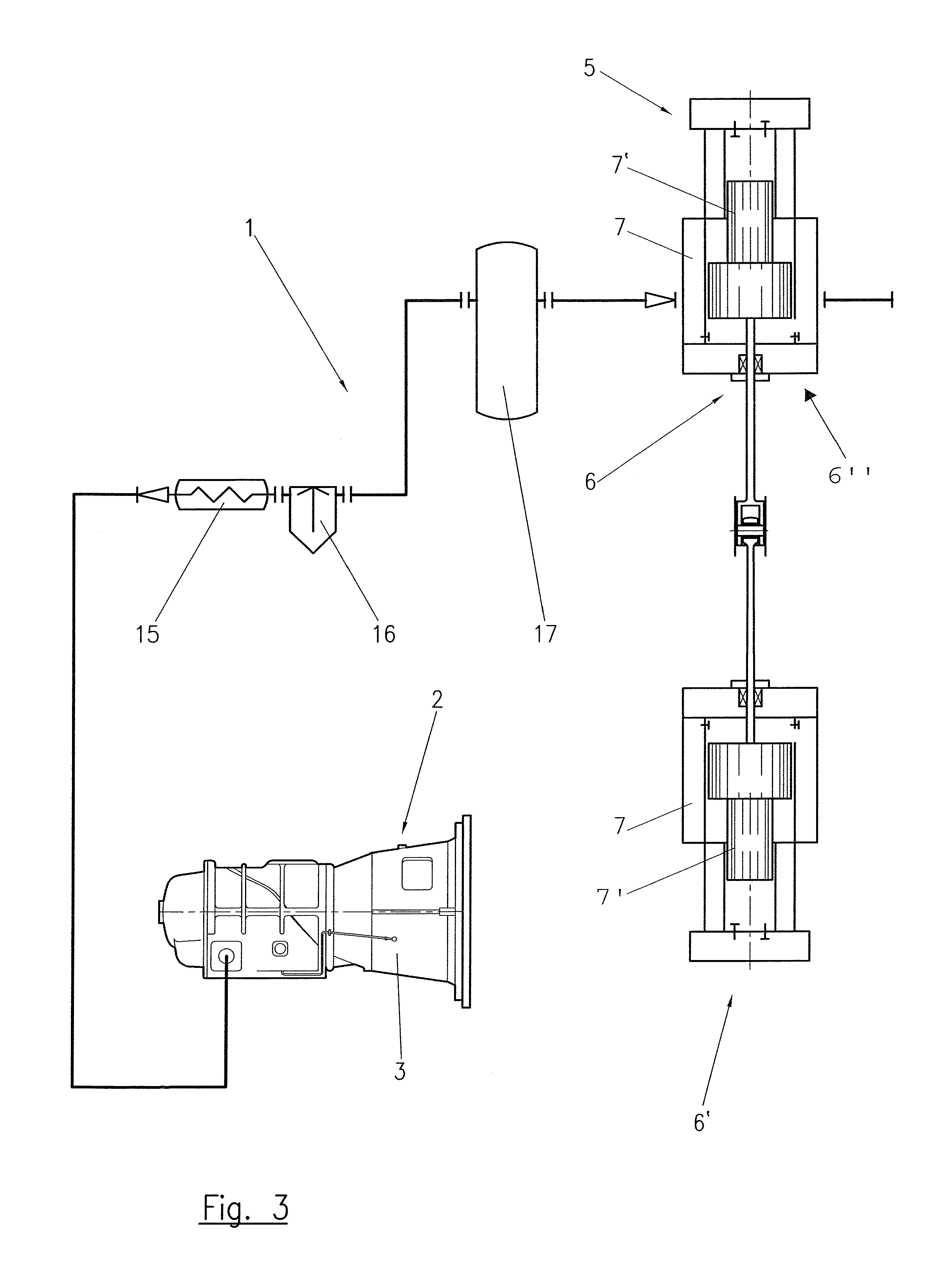
[0025]In FIG. 1, a multi-stage compressor 1 is shown, wherein a screw-type compressor 3 is provided in a low-pressure region 2. The screw-type compressor 3 is coupled to a central drive engine which drives the reciprocating piston compressor 6, likewise arranged in the high-pressure region 5, via a further crankshaft. Here, the reciprocating piston compressor 6 has two cylinders 7 arranged to be rotated relative to each other by 180° so that the reciprocating piston compressor 6 is designed in a so-called “boxer construction”, wherein the pistons 7′ received in the cylinders 7 (cf. FIG. 3) run on the same plane of motion. Here, the neutralization of forces of inertia of first order results in a high running smoothness of the reciprocating piston compressor 6 so that the multi-stage compressor 1 has an improved oscillation behavior compared to devices known. Moreover, a flat and short construction is achieved thereby so that the center of mass is low compared to known devices, what i...


PUM


Abstract

A multi-stage compressor (1) for compressing gases with a low-pressure region (2) and a high-pressure region (5), wherein at least one rotary compressor (3) is provided in the low-pressure region (2), and at least one reciprocating piston compressor (6) with two cylinders (7) is provided in the high-pressure region (5), and wherein a common engine (4) is provided for driving the rotary compressor (3) and the reciprocating piston compressor (6), wherein the cylinders (7) are arranged to be rotated relative to each other by 180° in the high-pressure region (5).

Description

FIELD OF THE INVENTION[0001]The invention relates to a multi-stage compressor for compressing gases with a low-pressure region and a high-pressure region, wherein at least one rotary compressor is provided in the low-pressure region, and at least one reciprocating piston compressor with two cylinders is provided in the high-pressure region, and wherein a common engine is provided for driving the rotary compressor and the reciprocating piston compressor.BACK OF THE INVENTION[0002]It has basically been known from WO 03 / 010436 A1 to combine a rotary compressor, in particular a screw-type compressor, in the low-pressure region with a reciprocating piston compressor in the high-pressure region. Here, a multi-stage reciprocating piston compressor is shown for high-pressure compressing of the gas to be compressed, wherein the cylinder of the individual compressor stages are arranged to be V-shaped towards each other. Here, the reciprocating piston compressor and the low-pressure compressor...

Claims


Application Information

Patent Timeline
IPC IPC(8): F04B23/12F04B3/00F04B5/00
CPCF04B25/00F04B25/005F04B25/02F04B27/02F04B39/06F04B23/106F04B41/06F04C18/16F04C23/005F04C23/02F04B23/12F04B39/16
Inventor HUTTAR, ERNST
Owner LEOBERSDORFER MASCHFAB
Why Eureka
Eureka Blog
Learn More