Eureka AIR delivers breakthrough ideas for toughest innovation challenges, trusted by R&D personnel around the world.

Constrained layer damper, and related methods

a damper and constrained technology, applied in the direction of synthetic resin layered products, domestic walls, vehicle components, etc., can solve the problems of affecting the sales and profitability of vehicles, materials that do not possess strong pressure sensitive adhesive characteristics at room temperature, and the difficulty of fixing the constrained layer damper to a substrate such as an automobile part, and may prove difficult or require expensive process equipment and procedures

Inactive Publication Date: 2013-02-19
MATERIALS SCI CORP
View PDF14 Cites 3 Cited by
  • Summary
  • Abstract
  • Description
  • Claims
  • Application Information

AI Technical Summary

Problems solved by technology

Consequently, the constrained layer dampers may significantly influence the sales and profitability of a vehicle.
While viscoelastic materials used in known constrained layer dampers may exhibit high peak damping temperatures such materials do not possess strong pressure sensitive adhesive characteristics at room temperature.
As the result of poor pressure sensitive adhesive characteristics, fixedly securing the constrained layer damper to a substrate, such as an automobile part, may prove difficult or require expensive process equipment and procedures.
Such constrained layer dampers lack the versatility to be applied and adequately secured to a substrate in room temperature environments.
Thin silicone layers may not wet out adequately, resulting in poor adhesion.
On the other hand, increasing the thickness of a silicone viscoelastic layer can adversely affect the constrained layer damper performance by reducing peak damping temperature of the damper below the operating temperature experienced by the damper in use.
Additionally, because silicone is relatively expensive compared to other damping materials, thick viscoelastic layers are economically undesirable.

Method used


Image

  • Constrained layer damper, and related methods
  • Constrained layer damper, and related methods
  • Constrained layer damper, and related methods

Examples


examples

[0061]The damping loss factor of a constrained layer damper having the multilayer damping material set forth in Table 2 below was determined using the damping test of ASTM E756-04 Standard Test Method for Measuring Vibration-Damping Properties of Materials. For evaluation procedures, the base bar was aluminum having dimensions of 205 mm×40 mm×3.2 mm. Tests were carried out in modes 2, 3, and 4.

[0062]

TABLE 2TestingLayerMaterialDimensionsbase baraluminum205 mm × 40 mm × 3.2 mm(126 mil thickness)con-cold roll steel170 mm × 40 mm × 0.635 mmstraining(25 mil thickness)layervisco-acrylic170 mm × 40 mm × 0.025 mmelastic(1 mil thickness)layercarrier88-92 wt % ferrite powder170 mm × 40 mm × 0.76 mmlayer7-11 wt % polyisobutylene(30 mil thickness)(MW 1.9-2.3 × 10⁶)PSASee Table 1170 mm × 40 mm × 0.051 mm(2 mil thickness)

[0063]The test results are set forth in Table 3 below and illustrated in FIG. 5. The peak damping temperature value for modes 2, 3, and 4 each fell within a range of 50-100° C., ...


PUM

PropertyMeasurementUnit
peak damping temperatureaaaaaaaaaa
weight percentaaaaaaaaaa

Abstract

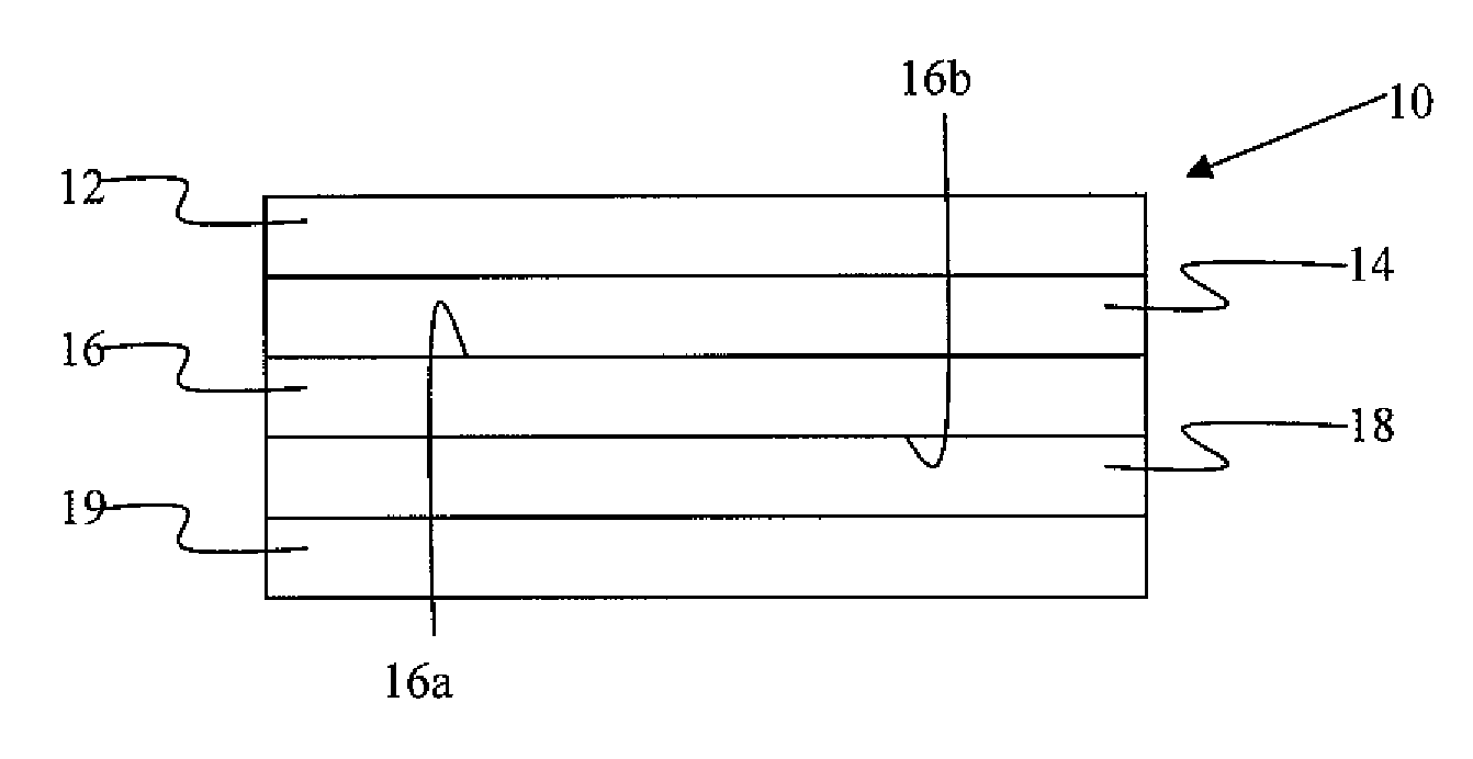
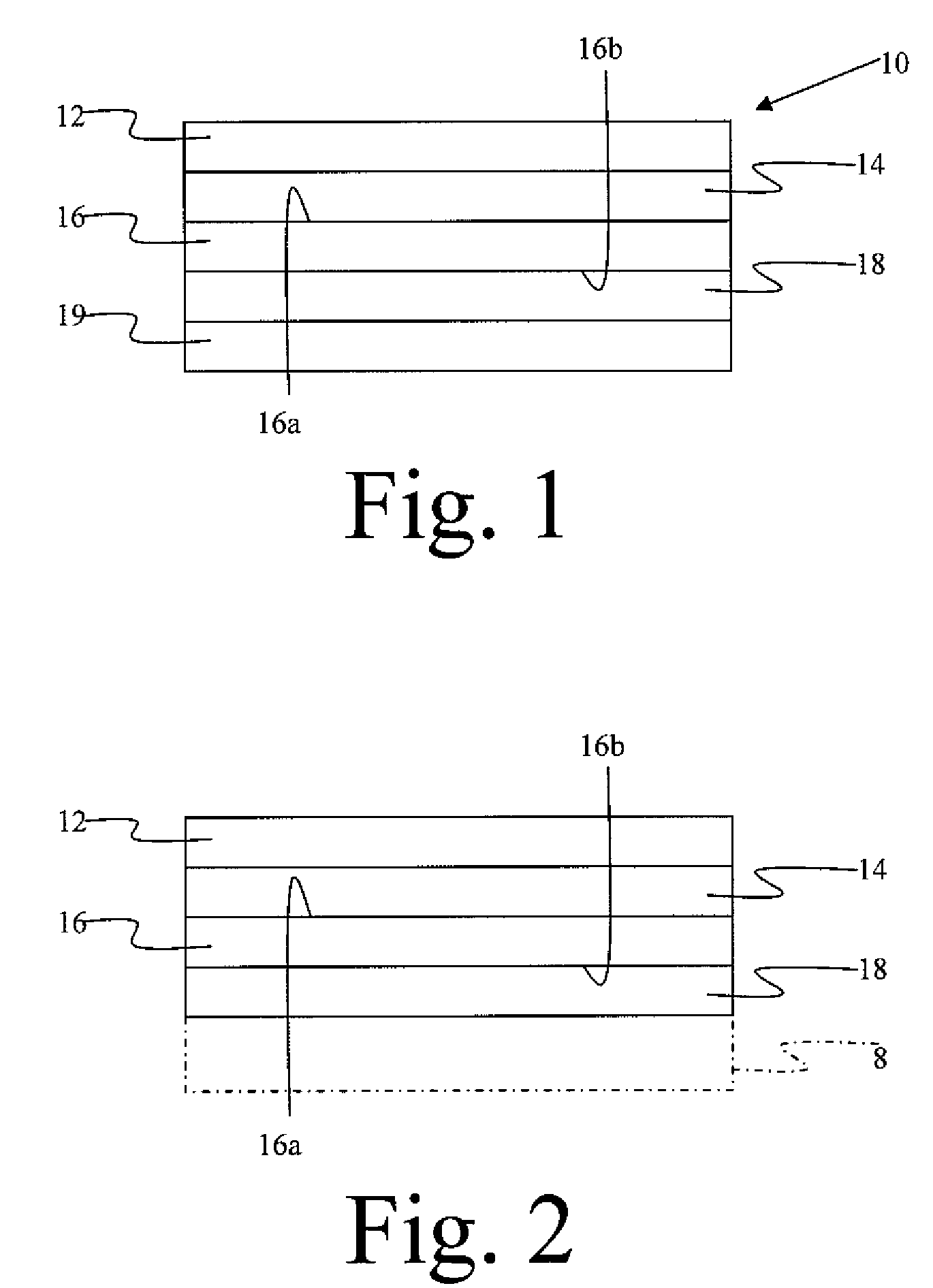
A constrained layer damper having a multilayer damping material is provided, as are related methods for making and using the damper. The constrained layer damper features a constraining layer, a carrier layer, a release liner, a viscoelastic layer interposed between the constraining layer and a first surface of the carrier layer, and a silicone pressure-sensitive adhesive interposed between the release liner and a second surface of the carrier layer. The silicone pressure-sensitive adhesive has sufficient tackiness at room temperature to adhere the constrained layer damper, with the release liner removed, to a substrate, such as a metallic substrate. The constrained layer damper has a peak damping temperature value in a range of about 50° C. to about 100° C.

Description

CROSS-REFERENCE TO RELATED APPLICATION(S)[0001]This application claims the benefit of priority of U.S. Provisional Application No. 60 / 992,420 filed Dec. 5, 2007, the complete disclosure of which is incorporated herein by reference.FIELD OF THE INVENTION[0002]This invention relates to constrained layer damper having a multilayer damping material, and to damped substrates and methods of making and using the dampers.BACKGROUND OF THE INVENTION[0003]Constrained layer dampers (CLDs) are known for their excellent damping characteristics and have found wide use throughout various industries. In the automotive industry, for example, constrained layer dampers are arranged about a vehicle passenger compartment for abating engine and outside noises and for deadening resonant vibrations experienced by the driver and passenger. The constrained layer dampers may be affixed to or incorporated into panels surrounding the passenger compartment. For example, the constrained layer dampers may be affix...

Claims


Application Information

Patent Timeline
Patent Type & Authority Patents(United States)
IPC IPC(8): B32B7/12B29C65/54
CPCB32B15/06B32B33/00F16F9/306B32B7/06B32B7/12B32B15/085B32B15/18B32B25/18B32B27/08B32B27/10B32B27/18B32B27/32B32B27/36B32B25/14Y10T428/2852B32B2307/56B32B2255/06B32B2255/102B32B2255/26B32B2264/102B32B2264/104B32B2264/105B32B2274/00B32B2307/748B32B2509/00B32B2605/00B32B2605/08B32B2605/12B32B2605/18B32B2607/00Y10T428/28Y10T428/1452Y10T428/1438Y10T428/1462Y10T428/2839Y10T428/2804Y10T428/1443Y10T428/1476
Inventor XIAO, HONG
Owner MATERIALS SCI CORP
Why Eureka
Eureka Blog
Learn More