
Protective sleeve to be arranged between two assembly elements for passing through cables/lines or the like in protective fashion and method for its production

a protective sleeve and assembly element technology, applied in the direction of machine supports, manufacturing tools, insulation bodies, etc., can solve the problems of problematic removal of the core, and achieve the effects of reducing the cost of parts or products, and reducing the cost of production

Active Publication Date: 2013-02-19
BAYERISCHE MOTOREN WERKE AG
View PDF15 Cites 0 Cited by
  • Summary
  • Abstract
  • Description
  • Claims
  • Application Information

AI Technical Summary

Benefits of technology

The present invention relates to a protective sleeve for cables or lines that pass through assembly openings. The protective sleeve is designed to securely fit the cables or lines and prevent water from entering through the assembly opening. The sleeve is made of a two-component part, with a rubber sleeve body and a hard-elastic plastic locking means. The locking means is formed in a separate mold and is over-molded with rubber, which provides better tightness and resilience. The protective sleeve has an opening cross-section that is larger than the sleeve body, allowing for easy removal of the core. The combination of rubber and plastic also allows for a small clearance between the inner width of the plastic frame and the outer diameter of the sleeve, while still enabling easy demolding. The protective sleeve can be installed in a motor vehicle by threading it through openings in the assembly elements. A hang-in hook is provided for simplified assembly. The invention solves the problem of providing a protective sleeve that is easy to install and securely fits the assembly opening.

Problems solved by technology

If locking means made of hard-elastic plastic are provided at both open ends of the sleeve body or its heads, the removal of the core is, however, problematic.
A particular problem arises if the heads are inclined relative to the longitudinal extension of the central portion.

Method used


Image

  • Protective sleeve to be arranged between two assembly elements for passing through cables/lines or the like in protective fashion and method for its production
  • Protective sleeve to be arranged between two assembly elements for passing through cables/lines or the like in protective fashion and method for its production
  • Protective sleeve to be arranged between two assembly elements for passing through cables/lines or the like in protective fashion and method for its production

Examples


Embodiment Construction

[0029]In the figures, the same parts are denoted by the same reference numerals.

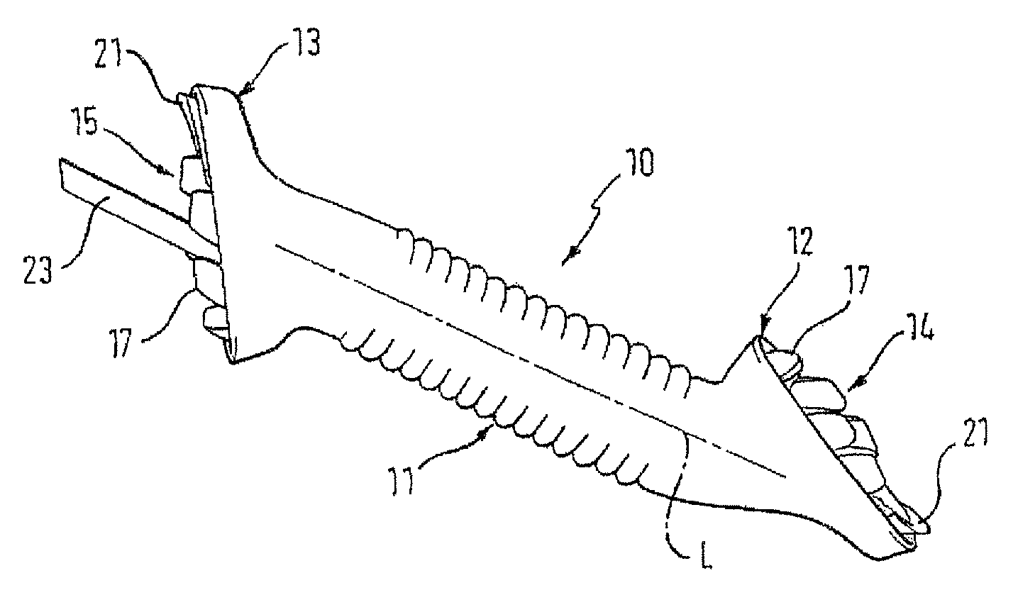
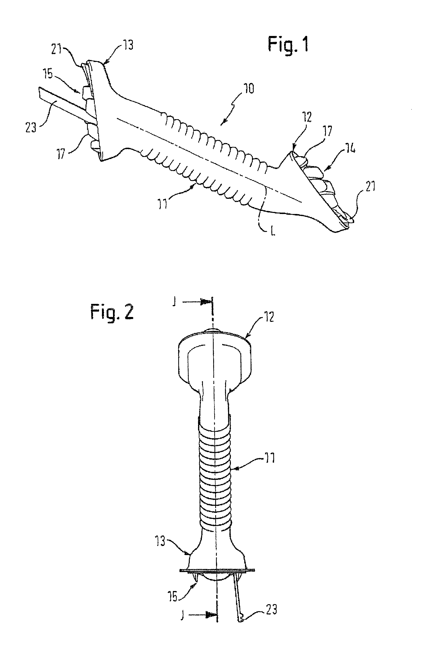
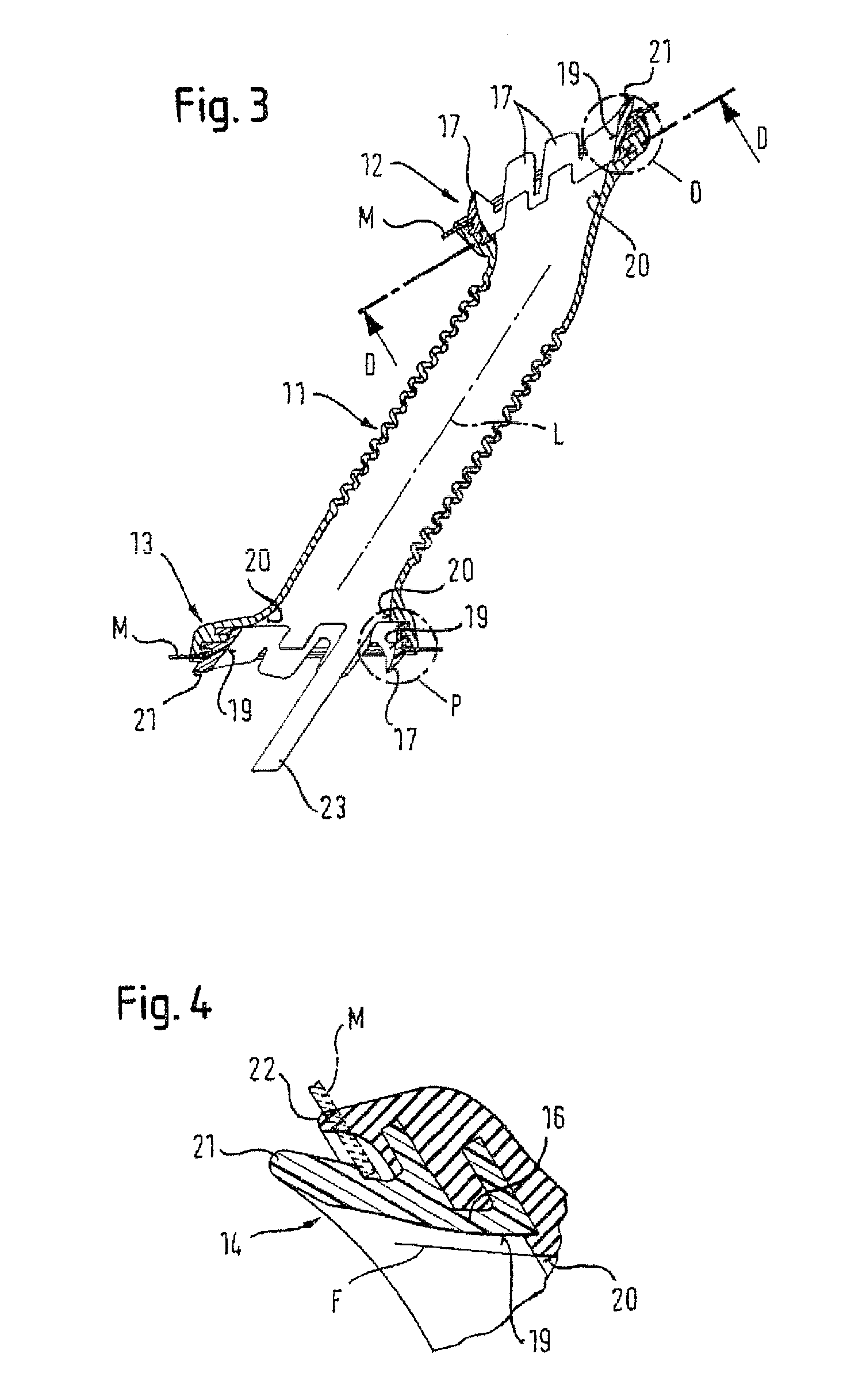
[0030]FIGS. 1 and 2 show a protective sleeve according to the present invention, which is suitable for arrangement between two assembly elements and for passing through cables / lines or the like. The inventive protective sleeve in FIG. 1 comprises an elongated tubular sleeve body 10. The sleeve body 10 comprises a substantially linear central portion 11 which in the illustrated embodiment is bellows-shaped. At its two opposite ends the central portion 11 is provided with a head 12 and 13, respectively.

[0031]Moreover, locking means 14 and 15 are formed at each of the heads, respectively. The locking means 14, 15 serve to button (fix) the protective sleeve into assembly openings of the assembly elements, which preferably are openings in car body walls of a motor vehicle, for instance between door or hatch and the body work. Moreover, the locking means 14, 15 are integrally formed with the sleeve body 10 so ...


PUM


Abstract

Bush to be arranged between two fitting elements for passing through cables, lines or the like in protected fashion, comprising an elongate, hose-shaped bush body (10) with a substantially linearly running central section (11) and heads (12, 13) at the ends, wherein the heads (12, 13) form a first inner circumferential face (20) at their open ends and a latching device (14, 15) for knocking the bush into installation openings in the fitting elements (M) is formed on each of the heads (12, 13) and integrally therewith, which latching device has a circumferential web (16) with at least one latching hook (17), which is formed thereon and has at least one radially outer latching tab (18), wherein the web forms a second inner circumferential face (19) opposite the latching tab (18), characterized in that the bush body (11) is formed from rubber and the latching devices (14, 15); are formed from hard-elastic plastic, and in that at least one of the second inner circumferential faces (19) is configured in such a way that it runs radially out of alignment with the corresponding first inner circumferential face (20).

Description

FIELD[0001]The present invention concerns a protective sleeve to be arranged between two assembly elements for passing through cables / lines or the like in a protected fashion and a method for its production. For example it concerns a protective sleeve for installation in motor vehicles and in particular between assembly elements such as the door or hatch and the body work. The present invention concerns in particular protective sleeves having an elongated tubular sleeve body having a central portion and head portions provided at its ends as well as a locking means for fixing (“buttoning in”) the protective sleeve in assembly openings of the assembly elements at each of the heads and integrally formed therewith, wherein the locking means comprise a circumferential rib (ridge) having at least one engagement hook formed thereon, which comprises at least one detent situated radially outside.BACKGROUND[0002]Such protective sleeves are known for example from DE 33 40 664 A1 and DE 100 58 ...

Claims


Application Information

Patent Timeline
Patent Type & Authority Patents(United States)
IPC IPC(8): H02G3/18
CPCB60R16/0222Y10T16/063Y10T16/05
Inventor BRUNNER, JOHANNBLUMBERG, ERICH
Owner BAYERISCHE MOTOREN WERKE AG
Learn More