Mobile wireless customizable health and condition monitor

a health and condition monitor, mobile technology, applied in the direction of diagnostic recording/measuring, instruments, applications, etc., can solve the problems of high vigilance, device reliability problems, and ineffective devices for patients with cognitive impairment, and achieve the effect of facilitating the user's heart ra

Inactive Publication Date: 2013-02-19
AFRAME DIGITAL
View PDF45 Cites 120 Cited by
  • Summary
  • Abstract
  • Description
  • Claims
  • Application Information

AI Technical Summary

Benefits of technology

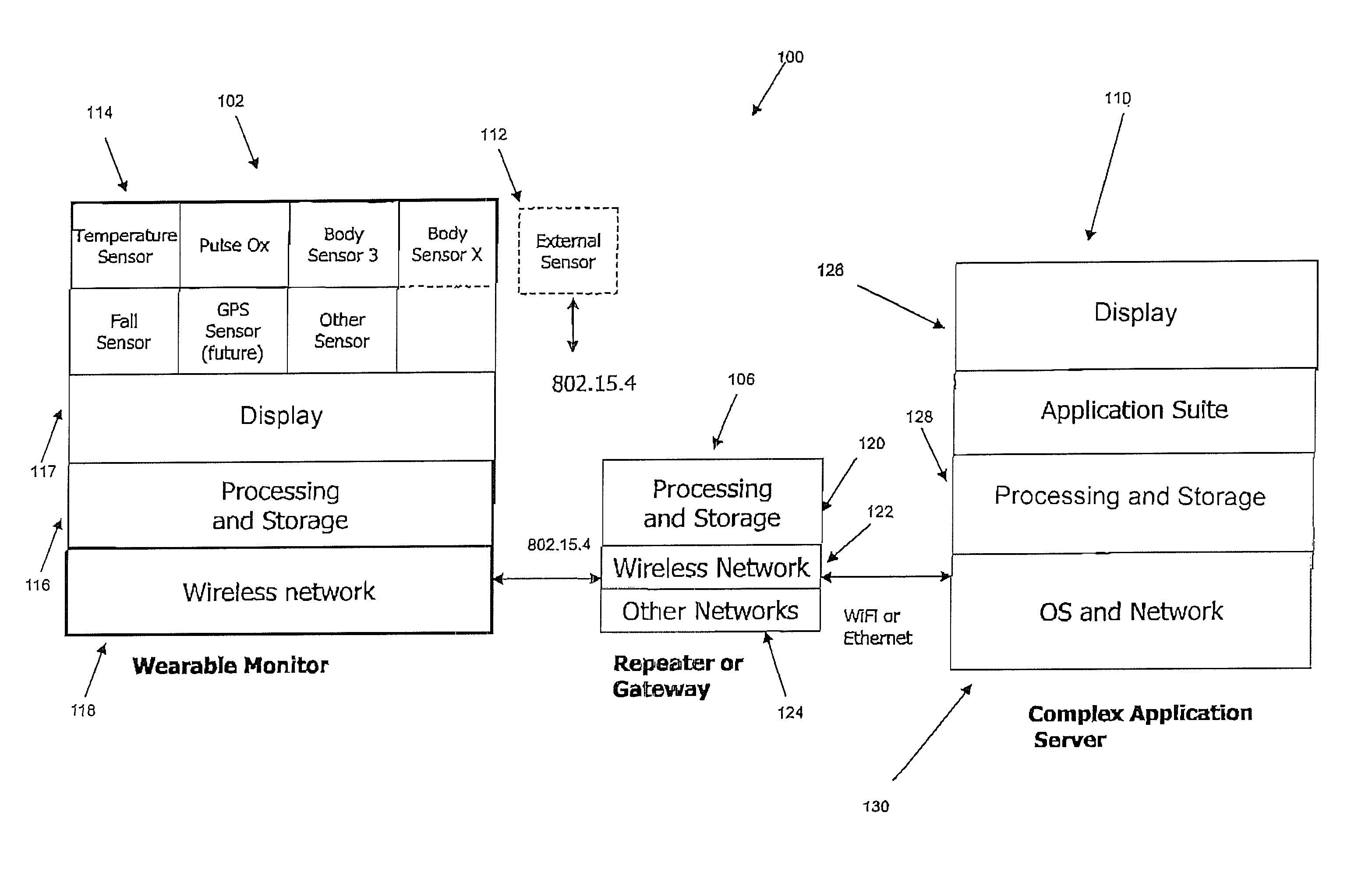
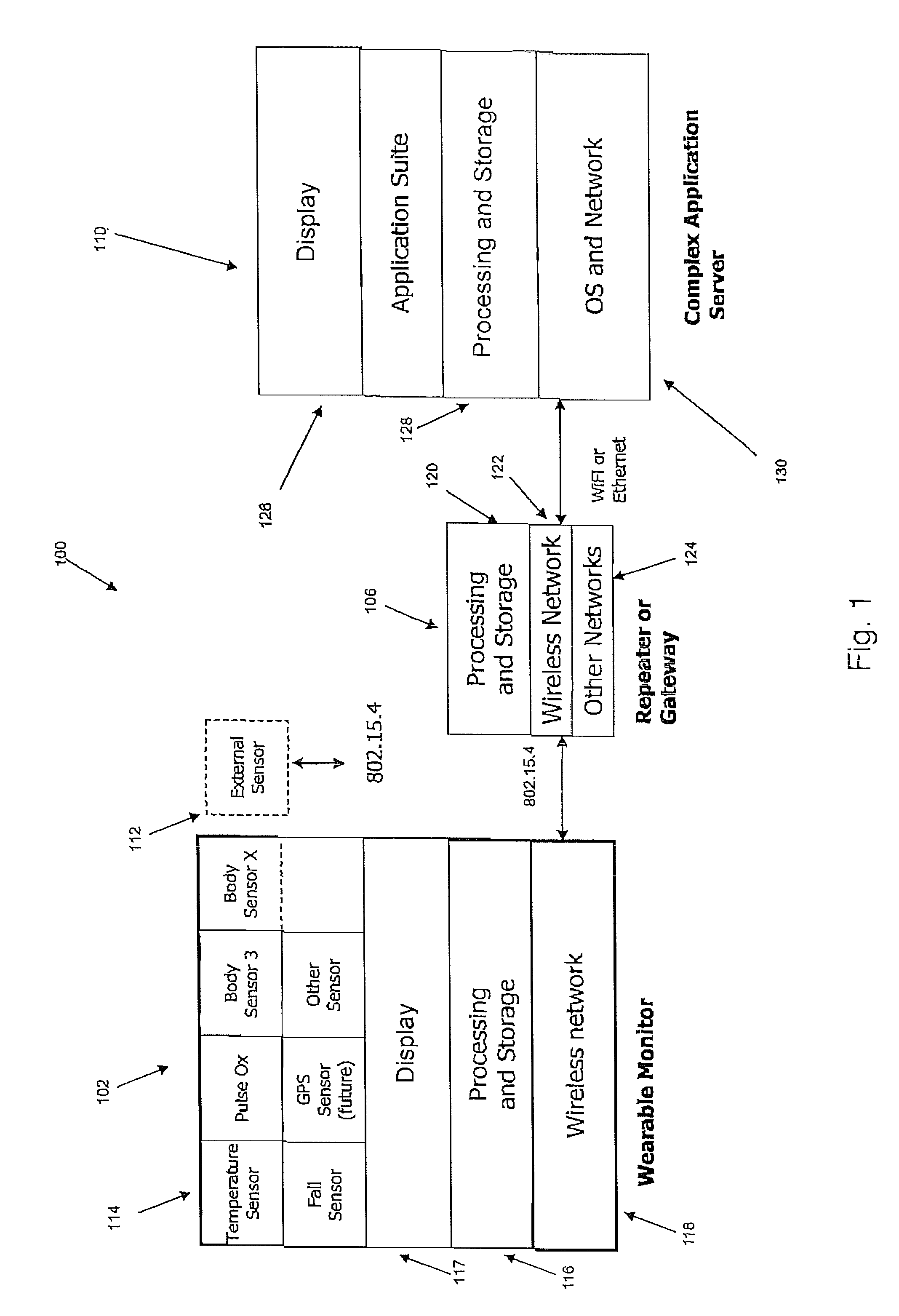
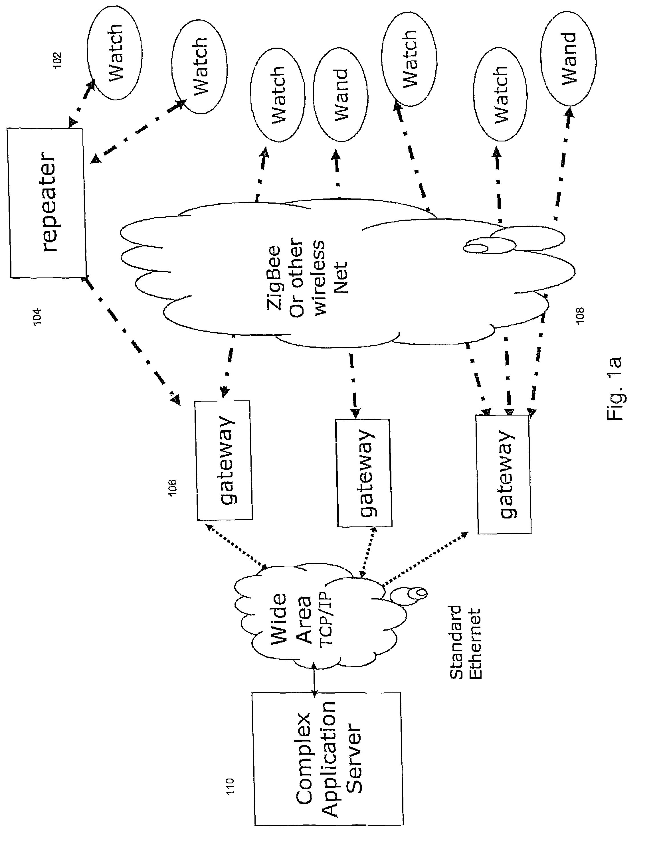
[0010]In another exemplary embodiment, a monitoring system may be provided. The monitoring system may include at least one wearable monitor coupled to a user, the at least one wearable monitor may include a timing mechanism; a plurality of sensor pairs coupled to the timing mechanism wherein each sensor pair comprises an emitter and a detector; and a microcontroller coupled in communication to the timing mechanism and the plurality of sensor pairs; at least one gateway having a second transceiver; at least one device located at a remote location; and at least one server coupled in communication using a wide area network to the at least one gateway and the at least one device, the at least one wearable monitor is coupled in wireless communication to the at least one gateway, the plurality of sensor pairs facilitate sensing a heart rate of the user and transmit the heart rate to the at least one server.

Problems solved by technology

These devices are capable of monitoring physiological functions, but are generally used in isolation and not integrated with other devices.
This type of device, however, is not effective for a patient who has a cognitive impairment (such as dementia) is knocked unconscious or otherwise rendered incapacitated by a fall or other medical condition.
These types of devices have reliability problems and require a high level of vigilance to constantly monitor the sensors.
Moreover, none of these devices is capable of delivering private, targeted and configurable alerts for designated caregivers, nor do they provide centralized data collection for automatic charting and close monitoring of individual patients.
This may be limited to checking a patient's vital signs only once a week due to the time and cost required to have staff to perform these duties.
However, when a patient's vital signs are checked only once a week, the declining health of a patient may only be detected after a health condition has worsened, eliminating the opportunity for early intervention.
Thus, there can be an increase in a care facility's patient morbidity and mortality rate.
Additionally, staff turnover and productivity can be an issue in care facilities that may need to spend more time replacing and training staff members to monitor sensors and patients' vital signs and to understand the patient's medical history and specific need for care.
These systems typically require significant wiring or installation of equipment within a home and can be uneconomical for either home or multi-patient facility use.
Moreover, motion detectors cannot distinguish between multiple residents or pets present in the home.
Additionally, this may only provide an inference, but not a direct and objective indication, of the patient's well-being.
Further, video-based services require a high level of attention to the video feeds from the cameras and the identity of the people can be difficult to discern.
There are additional issues in personal privacy and intrusion when using video or even motion detectors.
Additionally, it is not usually practical to have cameras or a video monitoring system in the house of a remotely located patient.
These devices, however, do not provide any other information besides the location of the wearer and they may not provide adequate transmission range.
Also, RFID is limited in its memory so very little processing is available and there is no 2-way processing of event monitoring data.
These devices, however, often fail to get an appropriate cellular signal inside health care facilities and again require significantly more power and have a battery life of hours thereby rendering such devices impractical for long-term monitoring.
Enabling devices with Bluetooth does not in itself bring about an integration of separate monitoring devices for one patient.
Indeed, there can be a limit of eight devices that may be joined together in a Bluetooth pico-net raising the question about scaling and the capacity to support hundreds of patients in a facility.
Merely replacing a cable from a monitor to a wireless Bluetooth-enabled equivalent can result in rapid battery depletion if continuous monitoring is attempted.
These devices, however, typically only have the ability to display the information collected on a display that is either worn on the individual or on separate display that the collected data is downloaded onto.
These devices, however, do not have the ability to transmit collected data on the individual back to a central location for analysis.
Further, these devices usually require a person to wear a variety of different sensors and can be intrusive on the person, embarrassing to wear, and prohibit some movement.
These devices also only allow a person to wear the device for a limited time, for example a few hours to several days, before the power source must be replaced or recharged.

Method used


Image

  • Mobile wireless customizable health and condition monitor
  • Mobile wireless customizable health and condition monitor
  • Mobile wireless customizable health and condition monitor

Examples


Embodiment Construction

[0029]Aspects of the present invention are disclosed in the following description and related figures directed to specific embodiments of the invention. Those skilled in the art will recognize that alternate embodiments may be devised without departing from the spirit or the scope of the claims. Additionally, well-known elements of exemplary embodiments of the invention will not be described in detail or will be omitted so as not to obscure the relevant details of the invention.

[0030]As used herein, the word “exemplary” means “serving as an example, instance or illustration.” The embodiments described herein are not limiting, but rather are exemplary only. It should be understood that the described embodiments are not necessarily to be construed as preferred or advantageous over other embodiments. Moreover, the terms “embodiments of the invention”, “embodiments” or “invention” do not require that all embodiments of the invention include the discussed feature, advantage or mode of op...


PUM


Abstract

A wearable sensor may be provided. The wearable sensor may include a timing mechanism; a plurality of sensor pairs coupled to the timing mechanism wherein each sensor pair comprises an emitter and a detector; and a microcontroller coupled in communication to the timing mechanism and the plurality of sensor pairs.

Description

CROSS-REFERENCE TO RELATED APPLICATIONS[0001]This application is a continuation-in-part of U.S. patent application Ser. No. 11 / 371,071, filed Mar. 9, 2006 now U.S. Pat. No. 7,616,110, and entitled MOBILE WIRELESS CUSTOMIZABLE HEALTH AND CONDITION MONITOR, which claims priority under 35 U.S.C §119 to U.S. Patent Provisional Application No. 60 / 660,342, filed Mar. 11, 2005. The disclosures of the above-referenced applications are incorporated by reference herein in their entireties.BACKGROUND OF THE INVENTION[0002]Nursing homes and assisted care facilities employ a number of different methods and devices to monitor their patients. These devices are capable of monitoring physiological functions, but are generally used in isolation and not integrated with other devices. Some devices include fall alert buttons that require a patient to actively push a button to alert the staff of a care facility of a fall. This type of device, however, is not effective for a patient who has a cognitive im...

Claims


Application Information

Patent Timeline
Patent Type & Authority Patents(United States)
IPC IPC(8): G08B1/08G08B23/00A61B5/00G16Z99/00
CPCA61B5/02055A61B5/02427A61B5/1117G08B21/0211G08B21/0446A61B5/0022A61B5/1112A61B5/14551A61B2562/0219A61B2562/0233A61B2562/046G16H40/67G16Z99/00
Inventor CRUMP, CINDY A.WILSON, BRUCE G.VIDETICH, JOHN
Owner AFRAME DIGITAL
Why Eureka
Try Eureka